Passive reflective imaging for visualizing subsurface structures in earth and water

a reflective imaging and subsurface technology, applied in seismic imaging, instruments, measurement devices, etc., can solve the problems of increasing the cost of seismic imaging, difficult to utilize active seismic sources in rugged terrain or in populated areas, and no practical acoustic lens has been developed to allow for focusing on subterranean objects using ambient noise. to achieve the effect of increasing the signal-to-noise ratio

Inactive Publication Date: 2009-03-05
SIMON WAYNE
View PDF18 Cites 10 Cited by
  • Summary
  • Abstract
  • Description
  • Claims
  • Application Information

AI Technical Summary

Benefits of technology

[0008]Adjusting the signals to focus on the subterranean point of interest may include time delaying at least a portion of each signal such that data associated with the point of interest in each of the signals is substantially aligned. In one arrangement, this includes time delaying each of the signals such that ray paths (e.g., the shortest path in time from the subterranean point of interest to an individual receiver) are equal for each of the receivers. In one arrangement, this includes moving each receiver along its respective ray paths to a position on a hypothetical spherical surface. In such an arrangement, the subterranean point of interest is the center of the spherical surface, and the time delay for each signal is based on a distance between the original location of the seismic receiver and the location on the spherical surface. Stated otherwise, each of the seismic sensors is moved onto a hypothetical acoustic lens surface (e.g., spherical surface) having a focal point located on the subterranean point of interest. This allows for calculating a time delay for each signal such that information in each of the signals that is received from the point of interest may be temporally aligned. Once aligned, they may be summed to increase the signal-to-noise ratio.

Problems solved by technology

For instance, it may be difficult to utilize active seismic sources in rugged terrain or in populated areas.
Further, use of such active seismic sources adds significantly to the cost of seismic imaging.
However, at present, no practical acoustic lens has been developed that allows for focusing on subterranean objects using ambient noise.

Method used


Image

  • Passive reflective imaging for visualizing subsurface structures in earth and water
  • Passive reflective imaging for visualizing subsurface structures in earth and water
  • Passive reflective imaging for visualizing subsurface structures in earth and water

Examples


Embodiment Construction

[0018]While the invention is susceptible to various modifications and alternative forms, specific embodiments thereof have been shown by way of example in the drawings and are herein described in detail. It should be understood, however, that it is not intended to limit the invention to the particular form disclosed, but rather, the invention is to cover all modifications, equivalents, and alternatives falling within the scope of the invention as defined by the claims. For instance, while in certain implementations as described below, the present invention utilizes passive seismic signals to generate subterranean images, some aspects of the present invention may be utilized with active seismic acquisition where one or more active seismic sources (e.g., explosives, vibrators, etc.) are utilized.

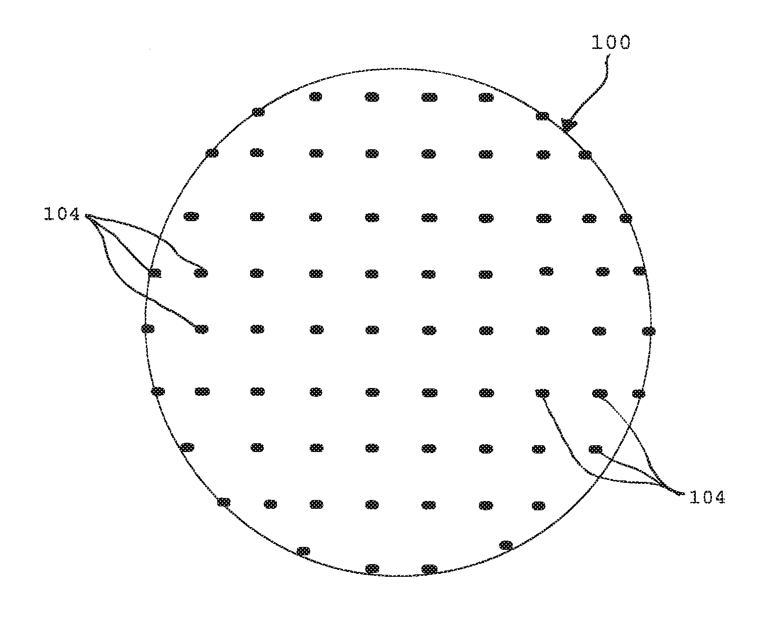
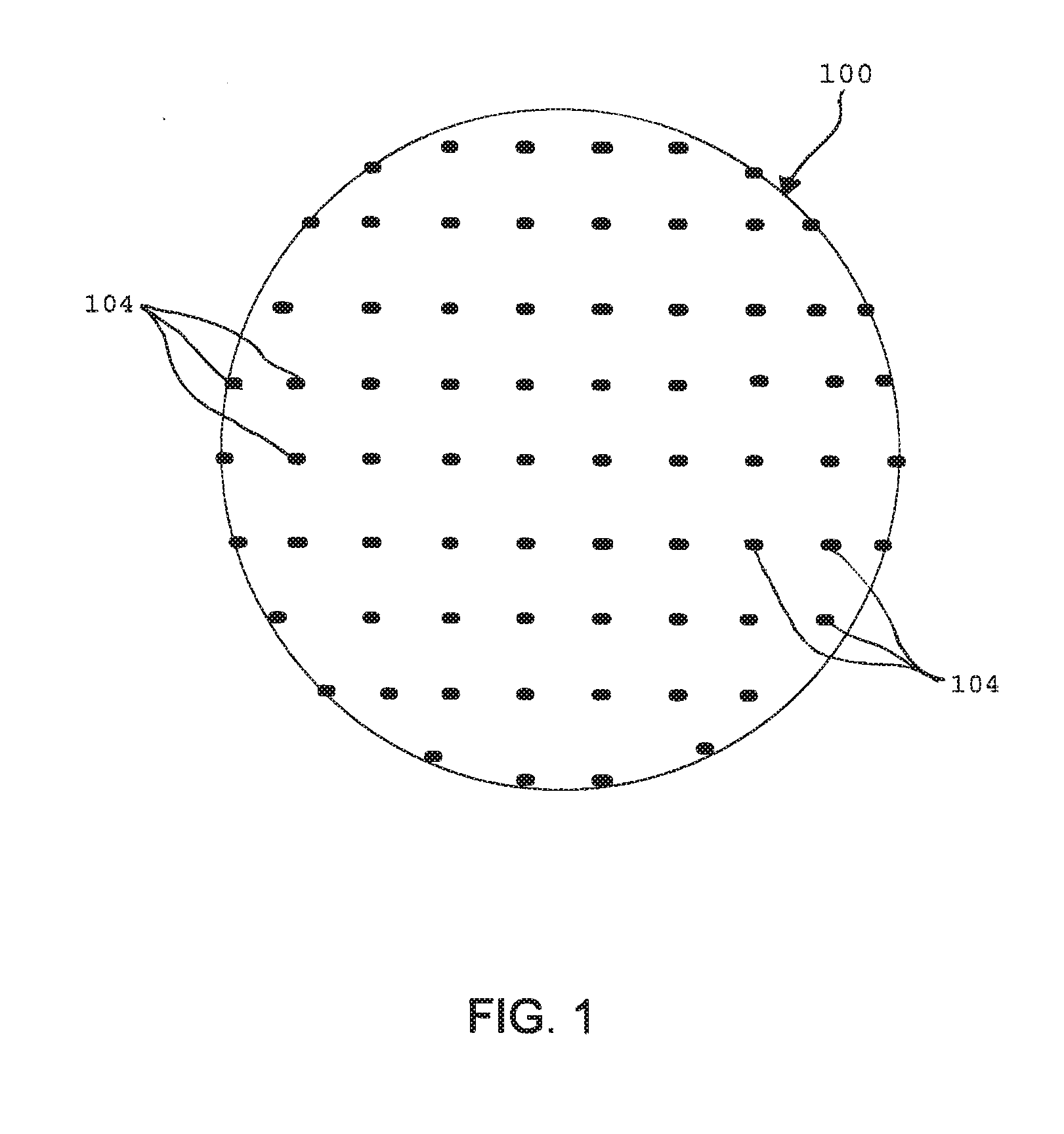
[0019]FIG. 1 depicts a physical layout of a seismic array 100 in accordance with one implementation of the present invention. In the present implementation, a number of data acquisition module...


PUM


Abstract

A system and method is provided that uses signals from a plurality of seismic sensors to define an acoustic lens for subsurface imaging. More specifically signals provided by an array of sensors / geophones may be utilized to form an acoustic lens that can be focused on a subterranean point by properly adjusting the signals recorded at each sensor prior to summation of those signals. To form such an acoustic lens, each of the seismic sensors is moved onto a hypothetical acoustic lens surface (e.g., spherical surface) having a focal point located on the subterranean point of interest in order to calculate a time delay for each signal. Once the signals for each sensor is time-delayed, information in the time-delayed signals, which is received from the point of interest, may be temporally aligned. Accordingly, the time delayed signals may be combined to generate reflection information for the point of interest.

Description

CROSS REFERENCE TO RELATED APPLICATION[0001]This application claims priority and the benefit of the filing date under 35 U.S.C. 119 to U.S. Provisional Application No. 60 / 951,042, entitled, “Passive Reflective Imaging for Visualizing Subsurface Structures in Earth and Water,” filed on Jul. 20, 2007, the contents of which are incorporated herein as if set forth in full.FIELD OF INVENTION[0002]The present invention relates to seismic exploration and underwater vision. More specifically, the present invention relates to passive seismic imaging that may be performed free of active seismic sources such as dynamite, vibrators, or air guns.BACKGROUND OF THE INVENTION[0003]In active seismic exploration, a subterranean area of interest is typically imaged by transmitting shots from active seismic sources and receiving reflected sonic / acoustic energy at multiple sensors / receivers (i.e., geophones or hydrophones) arranged in an array. The signals received at each geophone define a trace of sei...

Claims


Application Information

Patent Timeline
Patent Type & Authority Applications(United States)
IPC IPC(8): G01V1/28
CPCG01V2210/55G01V1/28
Inventor SIMON, WAYNE
Owner SIMON WAYNE
Why Eureka
Try Eureka