Beam irradiation device and laser radar

a beam irradiation and laser radar technology, applied in the direction of reradiation, distance measurement, instruments, etc., can solve the problems of laser light reflection timing, laser light emission timing, etc., and achieve high precision

Inactive Publication Date: 2009-03-05
SANYO ELECTRIC CO LTD +1
View PDF16 Cites 24 Cited by
  • Summary
  • Abstract
  • Description
  • Claims
  • Application Information

AI Technical Summary

Benefits of technology

[0019]In the above arrangement, a time difference between the two output timings of the electrical signals accurately corresponds to a time required for the laser light to reciprocate between the sc

Problems solved by technology

The dead space obstructs miniaturization of the beam irradiation device and the laser radar.
Also, since the lens diameter of the condenser lens is large, there is a problem that the size of the beam irradiation device and the laser radar may be increased in the lens diameter direction.
However, there is a case that

Method used


Image

  • Beam irradiation device and laser radar
  • Beam irradiation device and laser radar
  • Beam irradiation device and laser radar

Examples


first embodiment

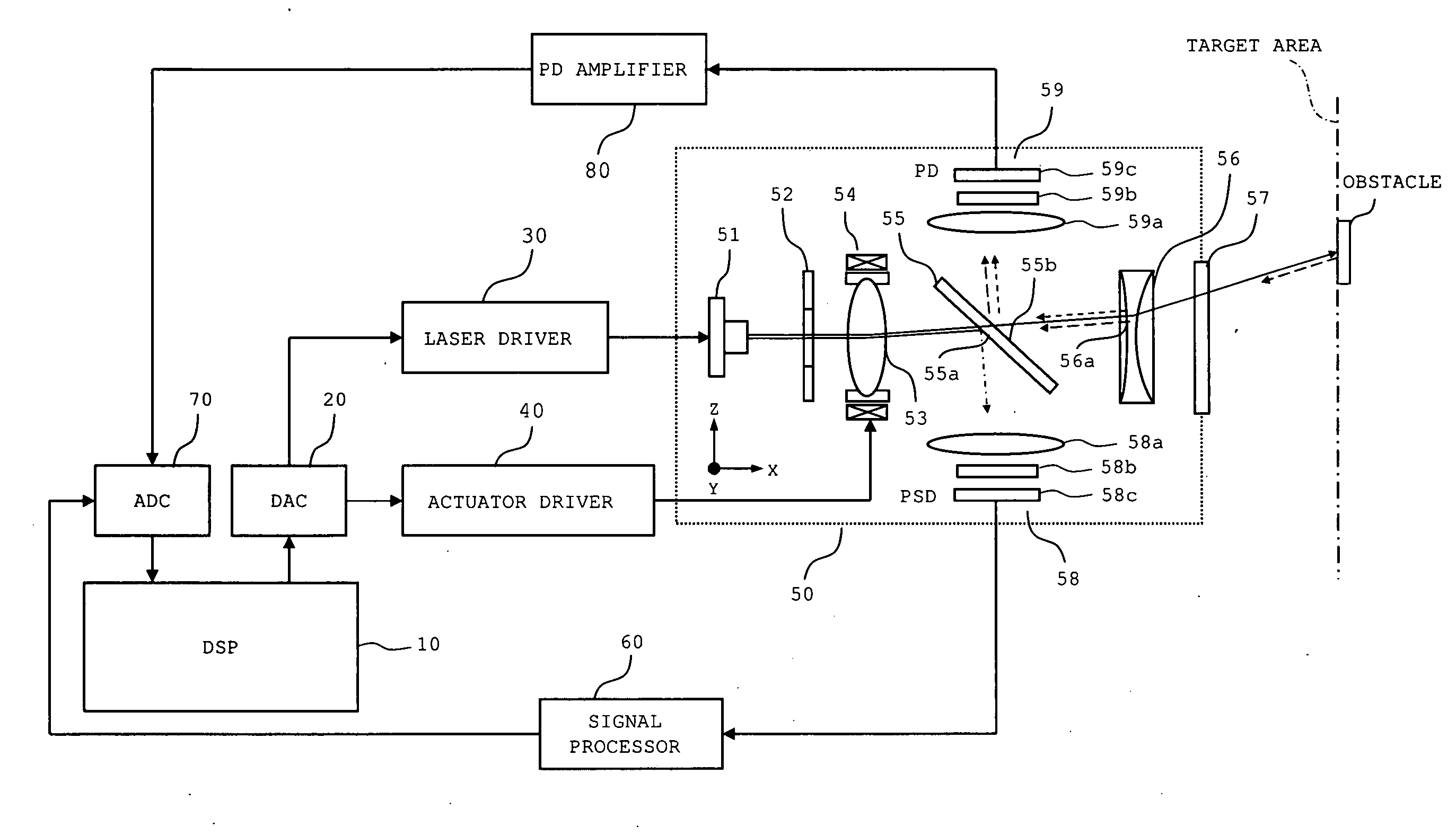
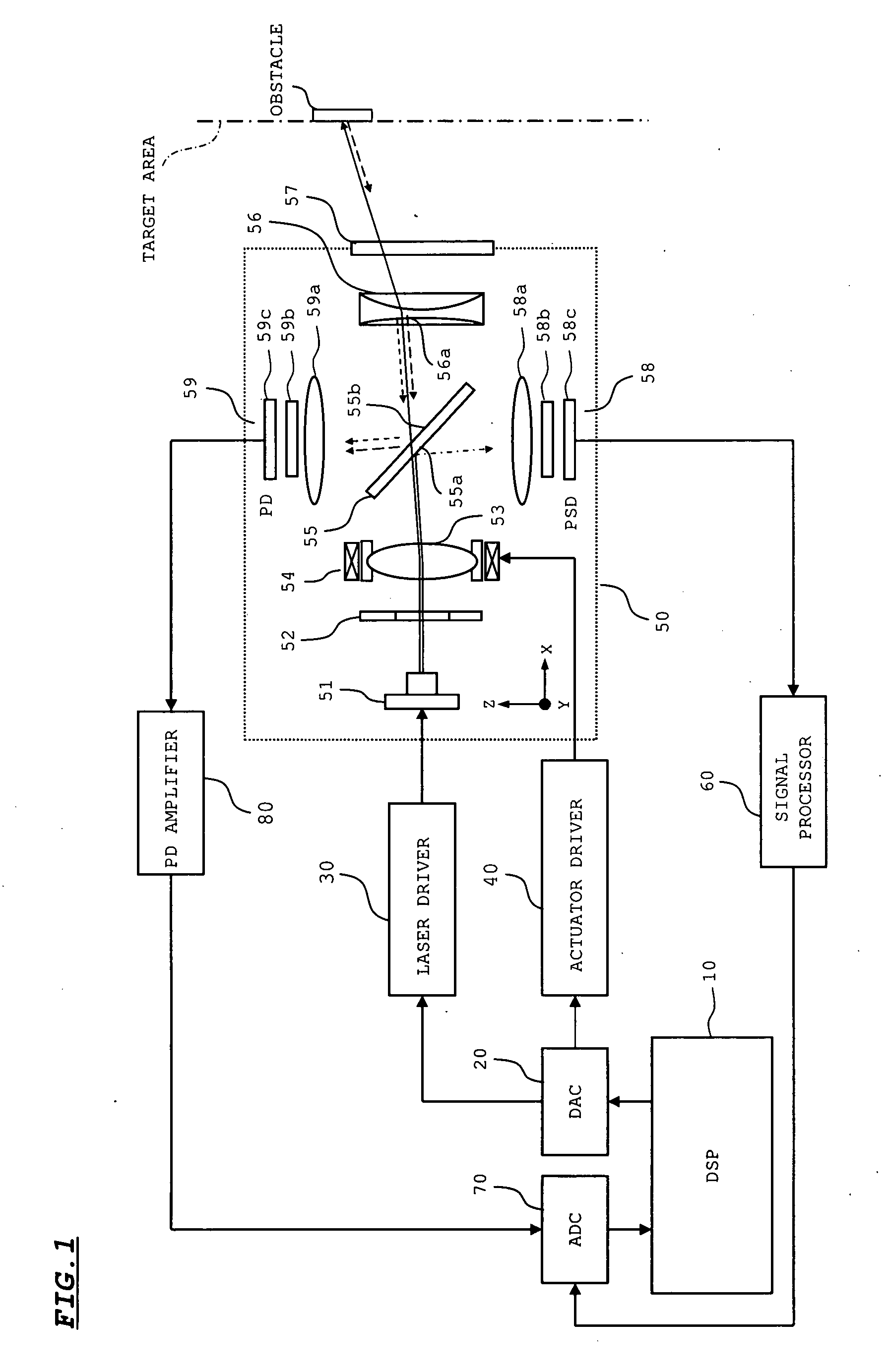
[0031]FIG. 1 is a diagram showing an arrangement of a laser radar in accordance with the first embodiment of the invention.

[0032]As shown in FIG. 1, the laser radar includes a DSP (Digital Signal Processor) 10, a DAC (Digital Analog Converter) 20, a laser driver 30, an actuator driver 40, a beam irradiation head 50 (corresponding to a beam irradiation device of the invention), a signal processor 60, an ADC (Analog Digital Converter) 70, and a PD amplifier 80.

[0033]The DSP 10 outputs, to the DAC 20, a signal (i.e. an emission signal) for emitting laser light, and a signal (i.e. a drive signal) for driving an actuator. The DAC 20 converts the emission signal inputted from the DSP 10 into an analog signal for outputting the analog signal to the laser driver 30, and converts the drive signal inputted from the DSP 10 into an analog signal for outputting the analog signal to the actuator driver 40.

[0034]The laser driver 30 drives a semiconductor laser 51 provided in the beam irradiation h...

second embodiment

[0071]FIG. 5 is a diagram showing an arrangement of a laser radar in accordance with the second embodiment of the invention.

[0072]In the second embodiment, a polarized beam splitter 550 is provided in place of the beam splitter 55 in the first embodiment. Also, a quarter wavelength plate 551 is provided between the polarized beam splitter 550 and a scan expansion lens 56. Further, a laser element, provided in a semiconductor laser 510, for emitting detection laser light has such a configuration that the polarization direction of detection laser light is aligned with the polarization direction of P-polarized light with respect to the polarized beam splitter 550. Likewise, a laser element, provided in the semiconductor laser 510, for emitting servo laser light has such a configuration that the polarization direction of servo laser light is aligned with the polarization direction of S-polarized light with respect to the polarized beam splitter 550. The other arrangement of the second e...

third embodiment

[0079]In the first embodiment and the second embodiment, the lens actuator 54 is used as displacing means for displacing the propagation direction of laser light. Alternatively, an actuator other than the lens actuator may be used to displace the propagation direction of laser light.

[0080]FIG. 6 is a diagram showing an arrangement of a laser radar in accordance with the third embodiment of the invention, wherein a mirror actuator 100 is used as an actuator.

[0081]In the embodiment, the mirror actuator 100 is arranged at a position posterior to a condenser lens 530. Laser light (i.e. detection laser light / servo laser light) emitted from a semiconductor laser 51 is reflected on a reflection mirror 531, and incident onto the condenser lens 530. Then, after convergence on the condenser lens 530, the laser light is incident onto a mirror 113 of the mirror actuator 100. The mirror actuator 100 is constructed in such a manner that the mirror 113 is pivotally rotated in horizontal direction ...


PUM


Abstract

A beam irradiation device includes a light source for emitting laser light, an actuator for displacing a propagation direction of the laser light in accordance with a control signal, and a scan expansion lens for increasing a swing width of the laser light to be generated by the actuator. A spectral element is arranged between the actuator and the scan expansion lens. The spectral element allows at least a part of the laser light to be incident from the actuator to transmit, and reflects at least a part of the laser light to be incident from the scan expansion lens. The beam irradiation device further includes a light detector for receiving the laser light to be reflected on the spectral element to output an electrical signal.

Description

[0001]This application claims priority under 35 U.S.C. Section 119 of Japanese Patent Application No. 2007-225288 filed Aug. 31, 2007, entitled “BEAM IRRADIATION DEVICE AND LASER RADAR”.BACKGROUND OF THE INVENTION[0002]1. Field of the Invention[0003]The present invention relates to a laser radar for irradiating laser light to a target area, and detecting a state of the target area based on a receiving state of the laser light reflected on the target area, and a beam irradiation device suitably used in the laser radar.[0004]2. Description of the Related Art[0005]In recent years, a laser radar for detecting a state of a target area by irradiating laser light to the target area has been loaded in a family automobile or the like. The laser radar is configured in such a manner that the target area is scanned with laser light to detect an obstacle (i.e. an object to be detected) based on a receiving state of reflection light from the target area, and at the same time, the distance to the ...

Claims


Application Information

Patent Timeline
IPC IPC(8): G11B7/00
CPCG01S7/4812G01S7/4813G01S7/4817G01S7/499G02B26/101G01S17/66G01S17/936G02B26/0875G01S17/42G01S17/931
Inventor YAMADA, MASATO
Owner SANYO ELECTRIC CO LTD
Why Eureka
Try Eureka