Eureka AIR delivers breakthrough ideas for toughest innovation challenges, trusted by R&D personnel around the world.

Network interface

a network interface and interface technology, applied in the direction of substation equipment, electrical equipment, interconnection arrangements, etc., can solve the problems of increasing line demand and associated bandwidth, nids employ plastic hinges which tend to fail with use, and the internet is expanded. to achieve the effect of durable and flexibl

Inactive Publication Date: 2009-03-05
SK COMMUNICATIONS
View PDF18 Cites 10 Cited by
  • Summary
  • Abstract
  • Description
  • Claims
  • Application Information

AI Technical Summary

Benefits of technology

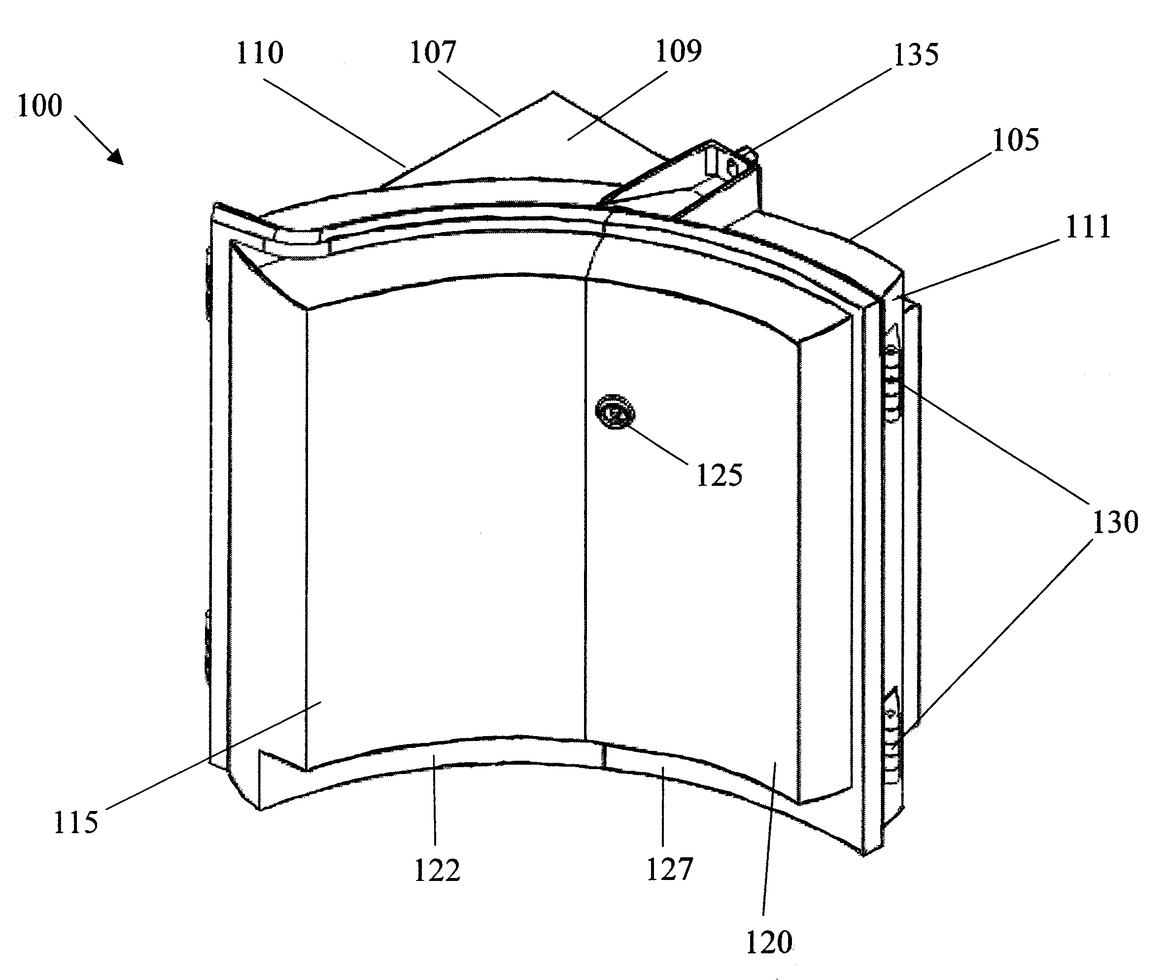
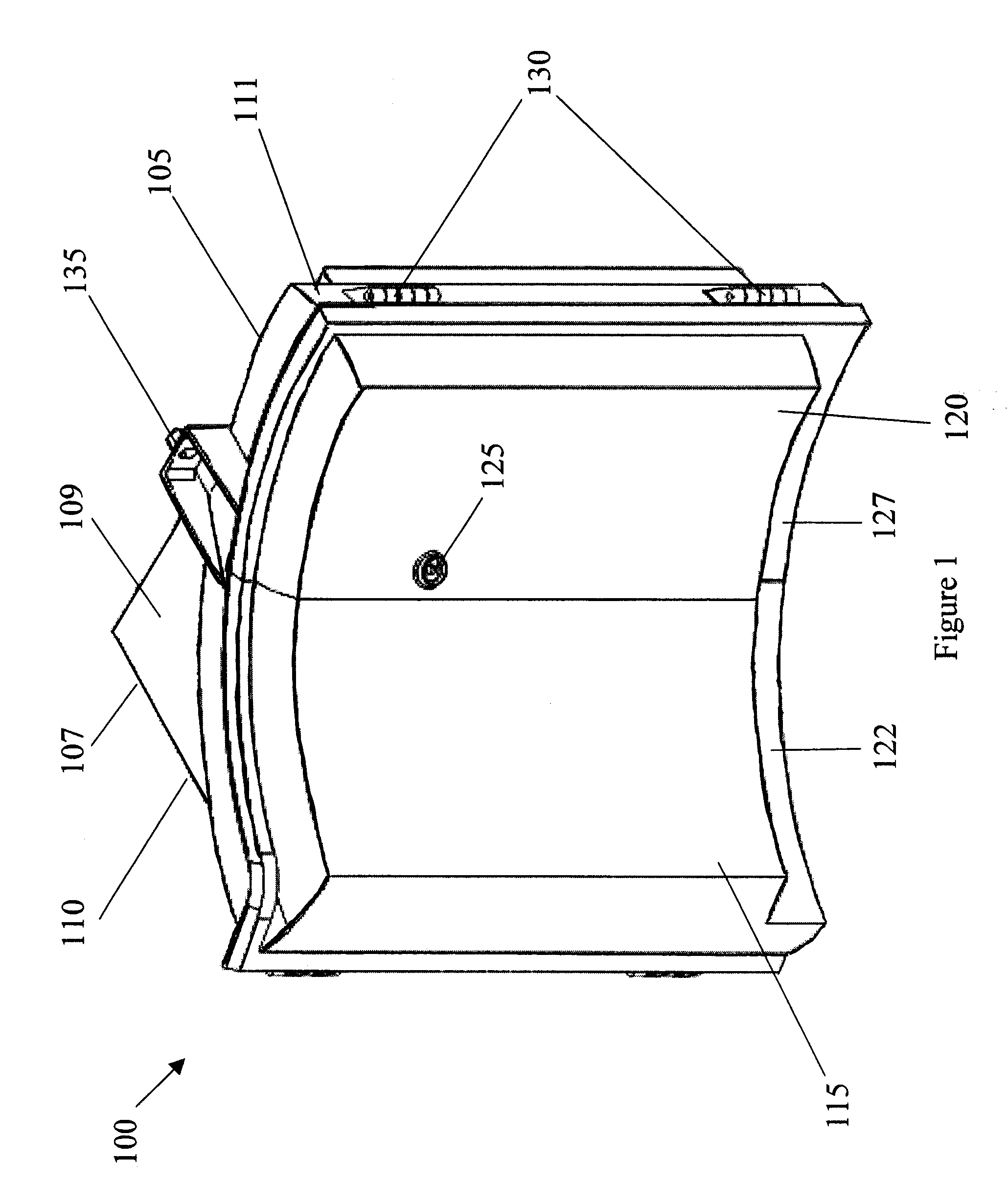
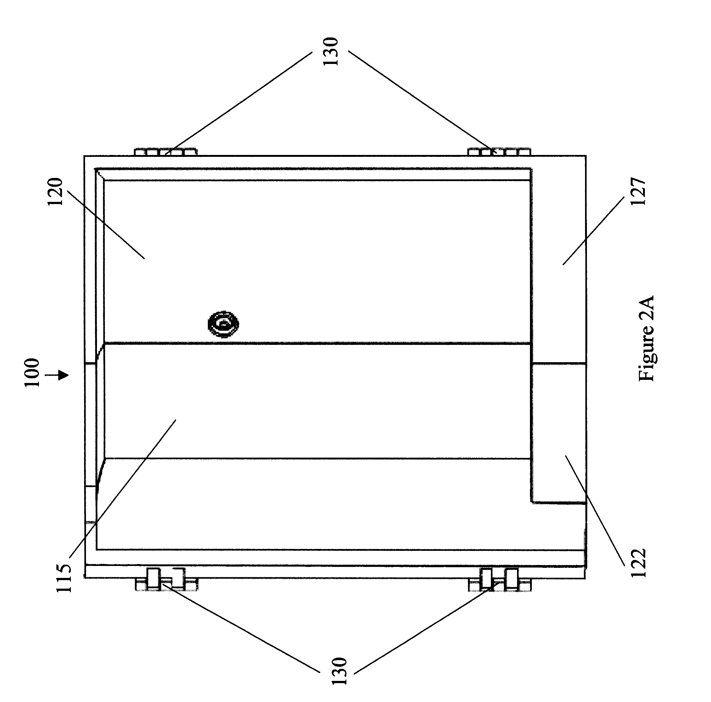
[0013]In another aspect, a network interface device is provided that includes a printed circuit board (PCB) comprising service provider interfacing circuitry and customer premise equipment (CPE) interfacing circuitry, an enclosable die-cast metallic housing for mounting the single printed circuit board therein, and means for protecting the service provider interfacing circuitry from access while the customer premise equipment (CPE) interfacing circuitry is being accessed.

Problems solved by technology

Most notably, expansion of access to the Internet has increased line demand and associated bandwidth.
Moreover, some traditional NIDs employ plastic type hinges which tend to fail with use.
Even though card modules have been used to implement advanced transmission protocols in high-density telecommunication environments, card modules rarely, if ever, find applications involving relatively few user lines, such as residences.
However, traditional NIDs typically do not permit front access to modules within the NID.
This approach is inconvenient for installers, and the extra door is another point of failure.
Further, traditional NIDs often employ a significant number of electrical connectors and / or flex cables to connect multiple internal electrical circuit boards, which are extra points of failure.

Method used


Image

  • Network interface
  • Network interface
  • Network interface

Examples


Embodiment Construction

[0029]It is understood that the invention is not limited to the particular methodology, protocols, etc., described herein, as these may vary as the skilled artisan will recognize. It is also to be understood that the terminology used herein is for the purpose of describing particular embodiments only, and is not intended to limit the scope of the invention. It is also to be noted that as used herein and in the appended claims, the singular forms “a,”“an,” and “the” include the plural reference unless the context clearly dictates otherwise. Thus, for example, a reference to “an address” is a reference to one or more addresses and equivalents thereof known to those skilled in the art.

[0030]Unless defined otherwise, all technical and scientific terms used herein have the same meanings as commonly understood by one of ordinary skill in the art to which the invention pertains. The embodiments of the invention and the various features and advantageous details thereof are explained more fu...


PUM


Abstract

A network interface device (NID) and associated printed circuit board is provided that includes metallic die cast housing and doors configured so that one of the doors, when closed, physically separates service provider circuitry from the customer premise equipment (CPE) side connections on a circuit card within the NID so that an end-customer may access the CPE side connections while the service provider circuitry remains secured from end-customer access. Moreover, the metallic housing provides increased physical strength and tamper resistance, including improved heat dissipation properties to radiate internal heat build-up more efficiently. The NID may be configured to provide insertable interface cards to permit flexibility in service provisioning and includes options for a type-200 T1 module, a type-400 T1 module, a type-200 high bit rate Digital Subscriber Line (HDSL) module, a type-400 HDSL module or an ISDN module.

Description

CROSS-REFERENCE TO RELATED APPLICATIONS[0001]This non-provisional application claims benefit of U.S. Provisional Application No. 60 / 969,405, filed Aug. 31, 2007, entitled DIE CAST OUTDOOR NETWORK INTERFACE ASSEMBLY (ONIA) DESIGNED TO HOUSE 2 OR 4 FRONT ACCESS DS1 / T1 / HDSLx CONNECTORS, the disclosure of which is hereby incorporated by reference herein in its entirety.BACKGROUND OF THE INVENTION[0002]1. Field of the Invention[0003]The invention is directed generally to a network interface device and, more particularly, to a die cast outdoor network interface device that includes various configurations such as to control access by service personnel separate from a consumer and improve surface mounting.[0004]2. Related Art[0005]The telecommunications industries, as well as other industries, continue to expand services to customers that include a variety of digital and analog voice, data and video applications. Most notably, expansion of access to the Internet has increased line demand an...

Claims


Application Information

Patent Timeline
Patent Type & Authority Applications(United States)
IPC IPC(8): H04M1/00
CPCH04M1/0293
Inventor CORRY, CHARLES D.GROTE, D. SCOTTEATON, EDWARDMATTHEWS, BRIAN W.
Owner SK COMMUNICATIONS
Why Eureka
Eureka Blog
Learn More