
Internal EMI Washer for Optical Transceiver with Parallel Optic Fiber Ribbon

Active Publication Date: 2009-03-05
SUMITOMO ELECTRIC DEVICE INNOVATIONS U S A
View PDF8 Cites 7 Cited by
  • Summary
  • Abstract
  • Description
  • Claims
  • Application Information

AI Technical Summary

Benefits of technology

[0007]Briefly, and in general terms, the claimed invention provides an optical transceiver for converting and coupling an information-containing electrical signal with a plurality of parallel optical fibers within an optical fiber ribbon. The optical transceiver includes the optical fiber ribbon and a housing permanently attached to the optical fiber ribbon. The housing includes a top portion and a bottom portion and an aperture for entry for the optical fiber ribbon. The optical transceiver also includes an electrical connector extending from the housing and an electro / optical converter disposed within the housing and coupled to the ribbon and to the electrical connector. The electro / optical converter includes an array of VCSELs and an array of photodiodes rigidly coupled to a ferrule supporting respective fibers of the fiber ribbon, the electro / optical converter converting between the information-containing electrical signal of the electrical connector and modulated optical signals corresponding to the electrical signal for transport over the optical fibers in the optical fiber ribbon. The optical transceiver further includes a strain relief bushing disposed on an outer surface of the housing adjacent the aperture that resists sharp bending of the optical fiber ribbon where the ribbon exits the housing through the aperture. A resilient, electrically conductive washer is disposed around the optical fiber ribbon within the aperture and between the optical fiber ribbon and housing, wherein the washer blocks leakage of electromagnetic radiation from the housing.

Problems solved by technology

As with any device operated at such a high frequency, optical transceivers generate significant electromagnetic interference (EMI).
Whenever the external housing is penetrated by an electrical or optical connection, the potential exists for EMI leakage.
Moreover, when a fiber ribbon is used, the EMI emitted may increase in direct proportion to the number of fibers in the fiber ribbon due to the larger hole.

Method used


Image

  • Internal EMI Washer for Optical Transceiver with Parallel Optic Fiber Ribbon
  • Internal EMI Washer for Optical Transceiver with Parallel Optic Fiber Ribbon

Examples


Embodiment Construction

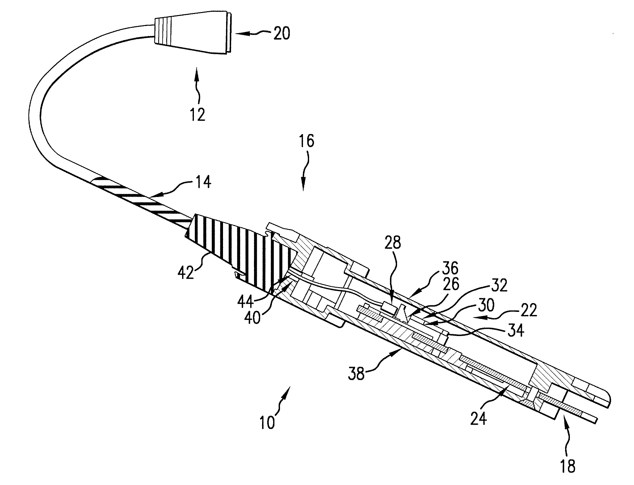
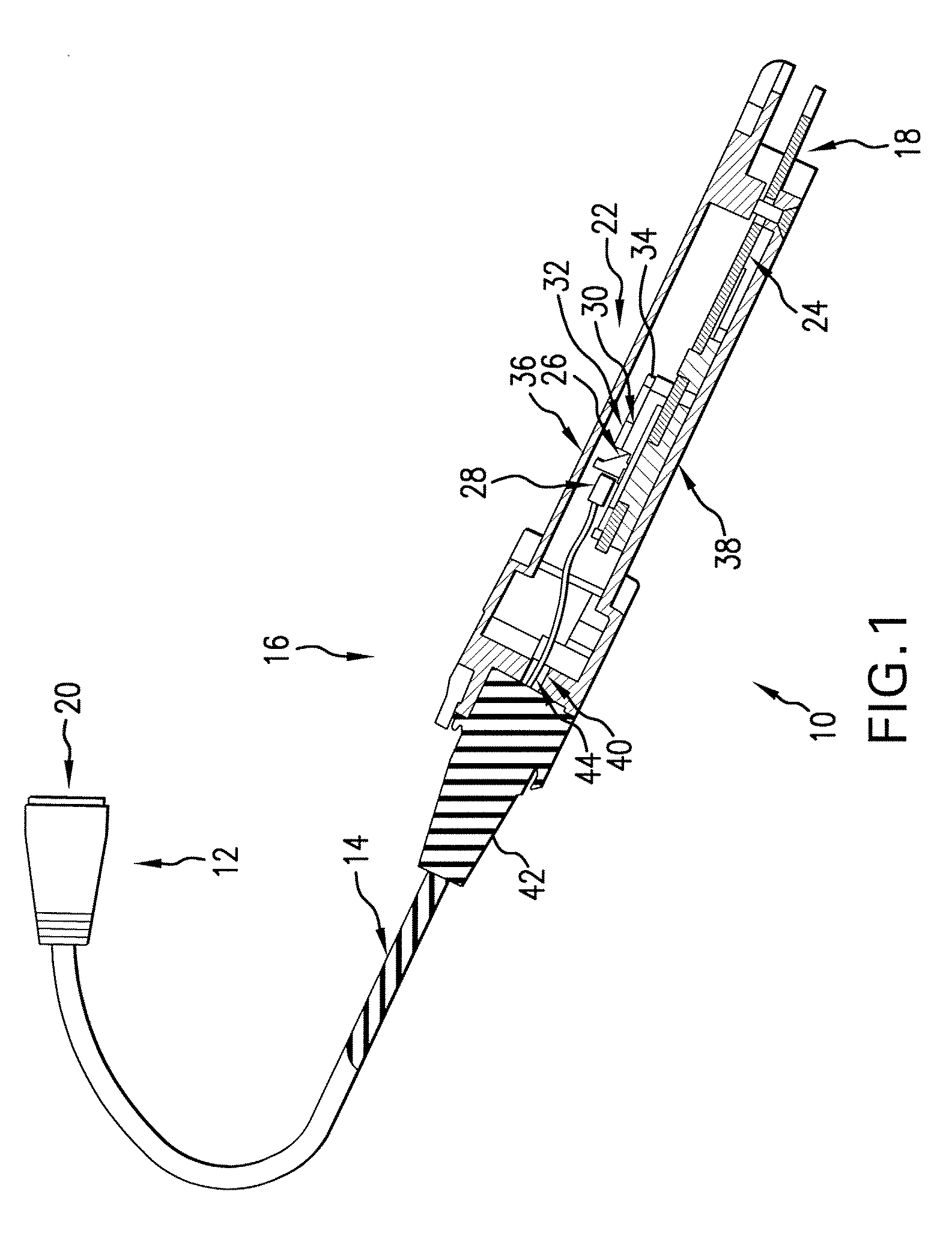
[0017]FIG. 1 is a partial cut-away side view of a communication cable 10 operating at some appropriate high-speed transmission rate (e.g., 10 Ghz) shown generally in accordance with an illustrated embodiment of the invention. The communication cable 10 provides a high speed communications link between information units (not shown) that may be located some distance apart. The information units may be host computers, Internet routers, etc.

[0018]The communication cable 10 may include a plug 12, 16 disposed on each opposing end of the cable 10. An electrical connector 18, 20 may be provided within each of the plugs 12, 16.

[0019]The electrical connectors 18, 20 on opposing ends are provided with sufficient electrical connector pins (e.g., a 100-pin Mega Array electrical connector) to exchange information signals between the information units under an appropriate multi-channel format (e.g., InfiniBand 4-channel, InfiniBand 12-channel, etc.). The plugs 12, 16 function to convert the inform...


PUM


Abstract

An optical transceiver including an optical fiber ribbon, a housing permanently attached to the optical fiber ribbon, and an electrical connector extending from the housing. An electro / optical converter is disposed within the housing including an array of VCSELs and an array of photodiodes rigidly coupled to a ferrule supporting respective fibers of the fiber ribbon. A member is disposed on an outer surface of the housing adjacent the aperture that resists sharp bending of the optical fiber ribbon where the ribbon exits the housing through the aperture and blocks leakage of electromagnetic radiation from the housing.

Description

FIELD OF THE INVENTION[0001]The field of the invention relates to optical communication systems and more particularly to an optical communication transceiver with a parallel optic fiber ribbon.BACKGROUND OF THE INVENTION[0002]High speed optical communications systems are generally known. Such systems typically include a transmitter optical subassembly (TOSA) and a receiver optical subassembly (ROSA) connected via an optical fiber.[0003]The TOSA may generally include one or more laser diodes. In some devices, an array of vertical cavity surface emitting lasers (VCSELs) are used to generate optical signals that are coupled through an optical fiber ribbon that includes an equal number of fibers. A corresponding array of photodetectors within the ROSA are used to detect a respective optical signal within each of the optical fibers of the fiber ribbon.[0004]The TOSA and ROSA are often operated in the GHz range. As with any device operated at such a high frequency, optical transceivers ge...

Claims


Application Information

Patent Timeline
IPC IPC(8): H04B10/00
CPCG02B6/4201G02B6/4246H04B10/40G02B6/4293G02B6/4277G02B6/424
Inventor WANG, CHARLES X.CHAN, SENG-KUMLAU, EDMONDMOSEBAR, ROBERT
Owner SUMITOMO ELECTRIC DEVICE INNOVATIONS U S A
Learn More