Trajectory based control of plasma processing

a technology of trajectory control and plasma processing, which is applied in the direction of individual semiconductor device testing, semiconductor/solid-state device testing/measurement, instruments, etc., can solve the problems of time-controlled multi-step etching with static set points and other desired processes or recipes of the prior art that may be considered too constraining, and the etching process of forming the contact structure of fig. 1 and most other etched structures is typically not straightforward,

Inactive Publication Date: 2009-03-05
APPLIED MATERIALS INC
View PDF4 Cites 12 Cited by
  • Summary
  • Abstract
  • Description
  • Claims
  • Application Information

AI Technical Summary

Benefits of technology

[0019]In one embodiment, multiple sequential trajectories may define an entire process. Preferably, the sequential trajectories are smoothly joined.

Problems solved by technology

The etching process of forming the contact structure of FIG. 1 and most other etched structures is typically not straightforward.
However, timing alone is not sufficient.
Nonetheless, time-controlled multi-step etching with static set points and other desired processes or recipes of the prior art may be considered to be too constraining in view of the narrow process window and continuously evolving etching environment.
If the etch process is not carefully controlled, etch stop may occur in which the etch rate falls to zero and the hole is never completely etched to its desired bottom.

Method used


Image

  • Trajectory based control of plasma processing
  • Trajectory based control of plasma processing
  • Trajectory based control of plasma processing

Examples


Embodiment Construction

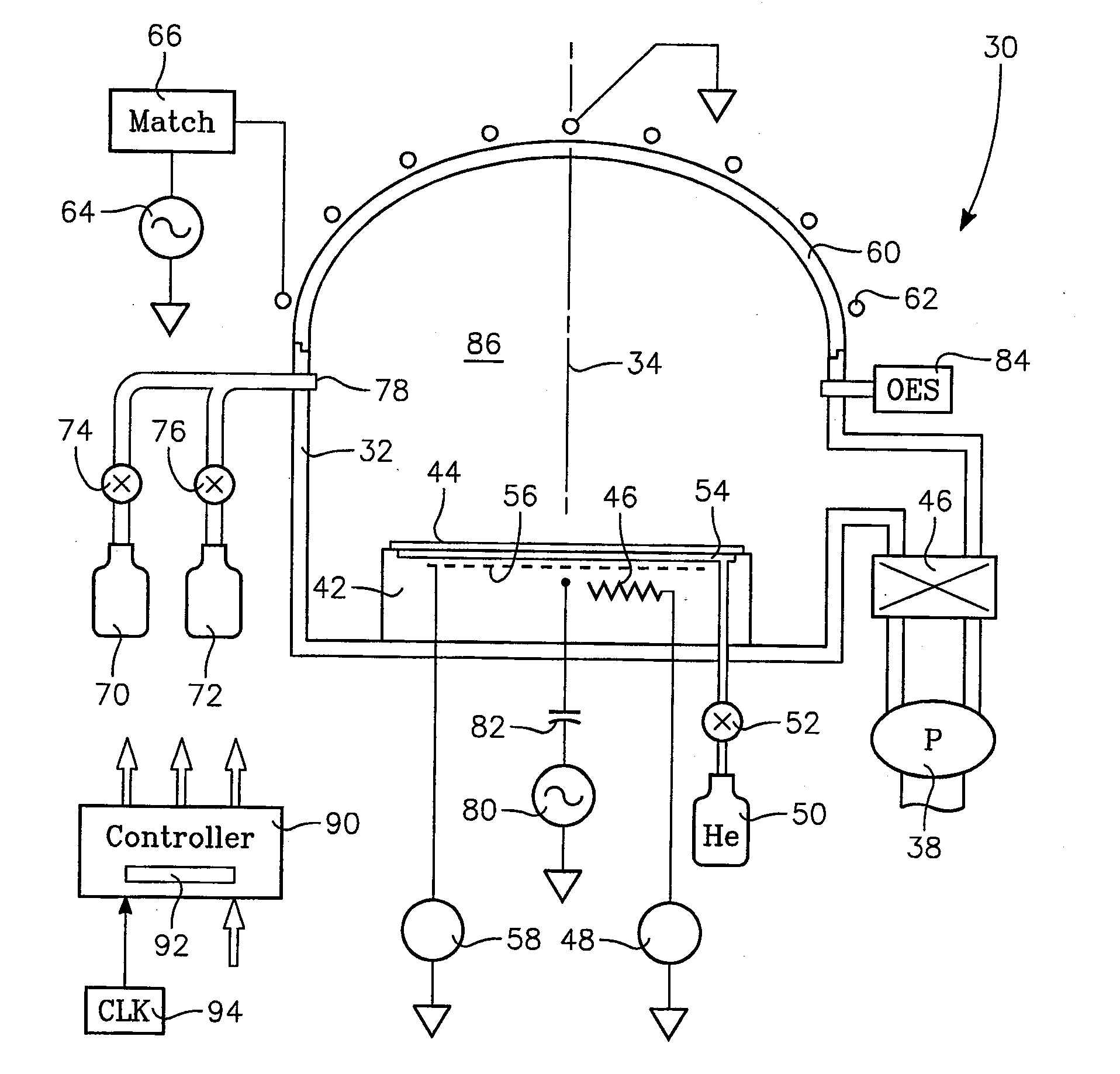
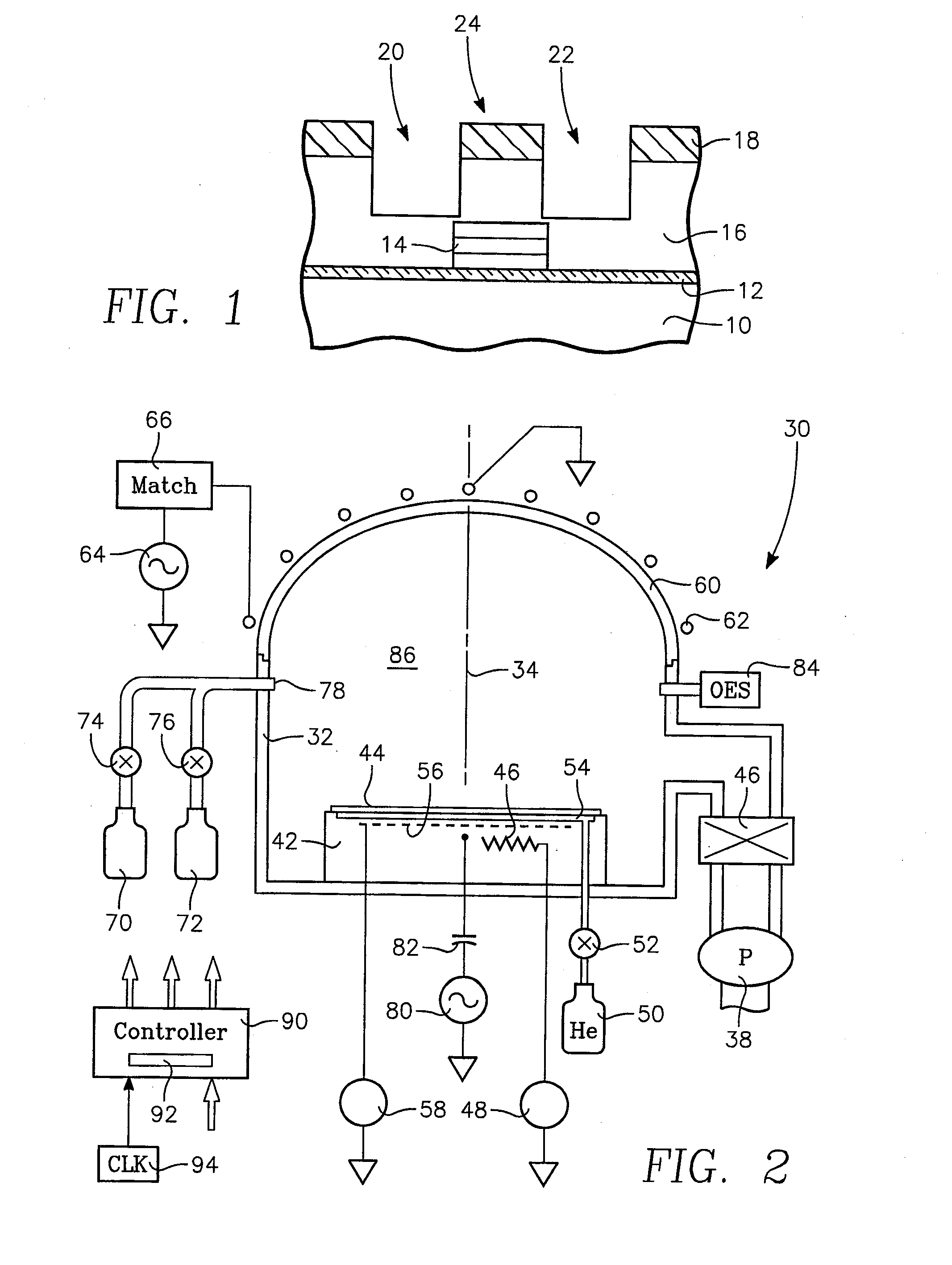
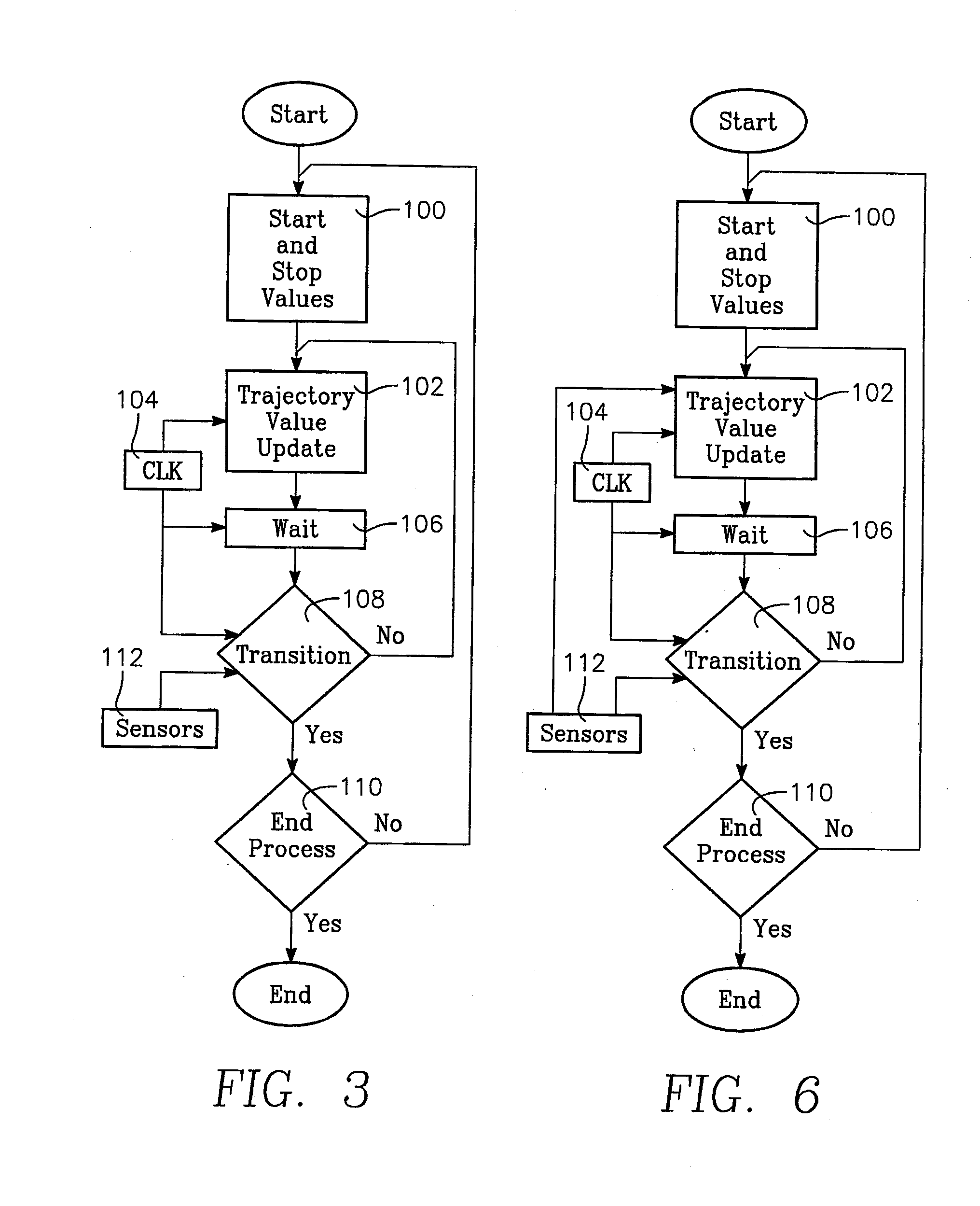
[0026]Embodiments of the present invention include a nearly continuous adjustment of process parameters rather than set levels of predetermined duration. A flow chart in FIG. 3 functionally illustrates an embodiment of the invention. At the start of processing a wafer, a set of start and stop values are provided at an initial values step 100. In one embodiment, a first phase of the process is selected for all controlled parameters such as chamber pressure, power levels, gas flows and the like. In one embodiment, the start and stop values represent the values of the controlled parameters at the beginning and end of the processing phase. The values are updated according to predetermined trajectories for each of the controlled parameters at an update step 102. In one embodiment, the start and stop values and the trajectories are stored in a controller memory as the recipe for the wafer process being practiced. The updating depends upon the elapsed time since the beginning of the phase ...


PUM

PropertyMeasurementUnit
timeaaaaaaaaaa
trajectoriesaaaaaaaaaa
poweraaaaaaaaaa

Abstract

A method of controlling a plasma processing according to trajectories connecting start and stop values of parameters controlling the plasma processing, for example, gas flow and power supplied to generate the plasma. The trajectories maybe based on equations including at least time as a variable. At set times within the processing, the values of the parameters are updated according to the predetermined trajectories. Sensors associated with the chamber may also adjust the trajectories, provide variables to the equations, and/or define the trajectories.

Description

RELATED APPLICATIONS[0001]This application claims benefit of provisional application 60 / 969,093 filed Aug. 30, 2007.FIELD OF THE INVENTION[0002]Embodiments of the invention relate generally to plasma processing of semiconductor substrates, such as plasma etch. In particular, embodiments of the invention relate to the control algorithm for regulating and terminating the plasma process.BACKGROUND ART[0003]Plasma etching is one of several plasma processing steps used to deposit, condition, etch, and otherwise process a semiconductor substrate, usually a silicon wafer. Electrical means excite a processing gas into a plasma and the highly reactive plasma gas acts upon the substrate. The process may include deposition, such as plasma enhanced chemical deposition (PECVD) or plasma sputtering from a target, conditioning of an already deposited layer to chemically change an already deposited material, or etching to remove a deposited material, usually in a patterned etch to selectively expos...

Claims


Application Information

Patent Timeline
Patent Type & Authority Applications(United States)
IPC IPC(8): H01L21/66H01L21/306
CPCH01J37/32935H01L22/26H01L21/32137H01J37/3299
Inventor HOLLAND, JOHN P.YAMARTINO, JOHN M.LILL, THORSEN B.SHEN, MEIHUAPATERSON, ALEXANDERTODOROW, VALENTIN N.
Owner APPLIED MATERIALS INC
Why Eureka
Try Eureka