Airflow Balance for a Twin Turbocharged Engine System

Inactive Publication Date: 2009-03-12
FORD GLOBAL TECH LLC
View PDF17 Cites 18 Cited by
  • Summary
  • Abstract
  • Description
  • Claims
  • Application Information

AI Technical Summary

Benefits of technology

[0004]Thus, the combination of sensor outputs from a mass airflow sensor of only one of the two branches and an output from one or more sensors arranged in a combined flow region of the intake system can be used to identify imbalance between the two branches. In this way, an imba

Problems solved by technology

One issue with twin turbocharged engines is that the amount of airflow provided by each of the turbochargers may become unbalanced.
For example, degradation or failure of a turbocharger or other component of the exhaust system or variations in engine system components may cause one of the turbochargers to provide a larger portion of the total airflow to the engine than the other turbocharger.
Thus, under these conditions, the engine system may generate noise and vibration harshness (NVH), experience reduced fuel efficiency, and/or the lower

Method used


Image

  • Airflow Balance for a Twin Turbocharged Engine System
  • Airflow Balance for a Twin Turbocharged Engine System
  • Airflow Balance for a Twin Turbocharged Engine System

Examples


Example

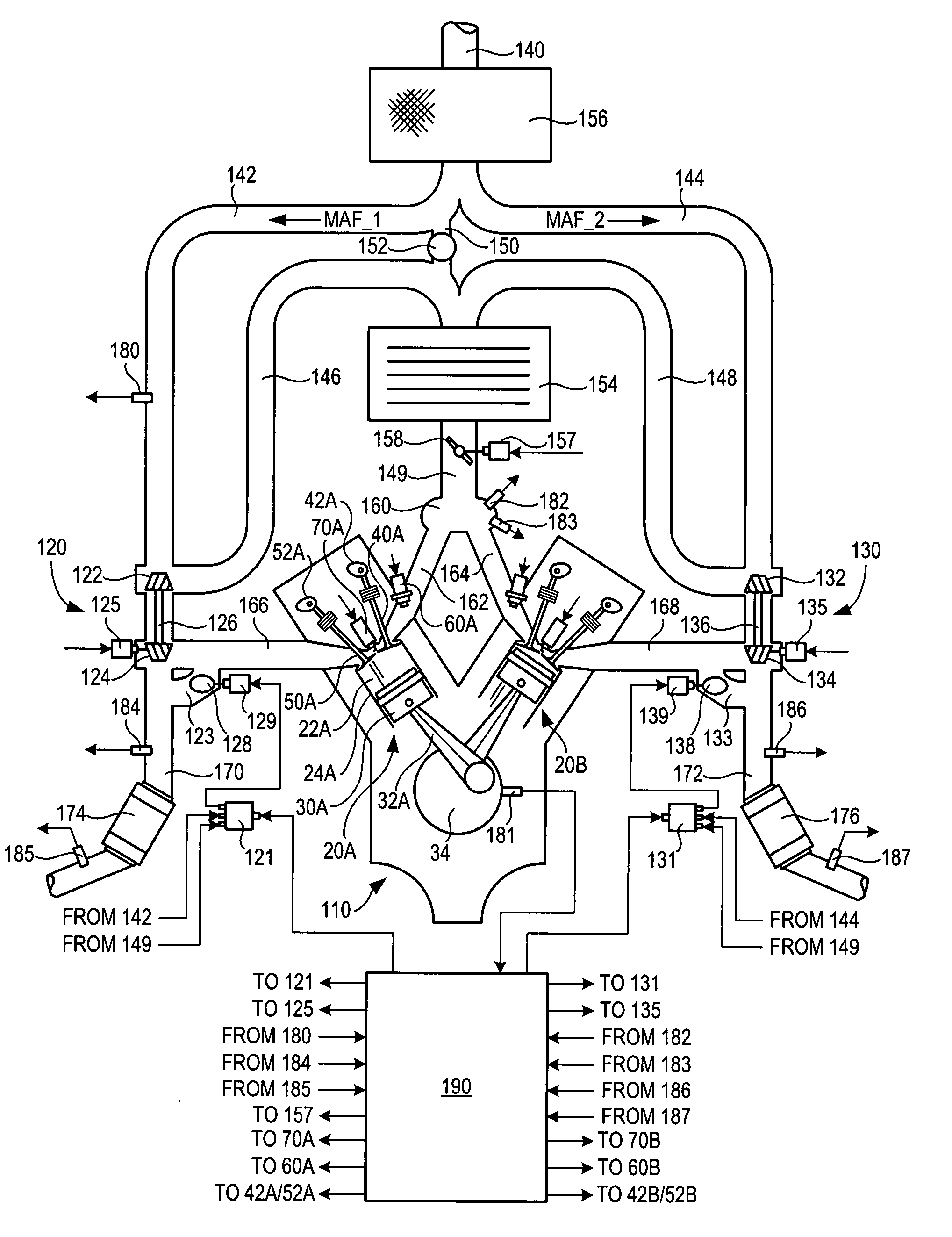
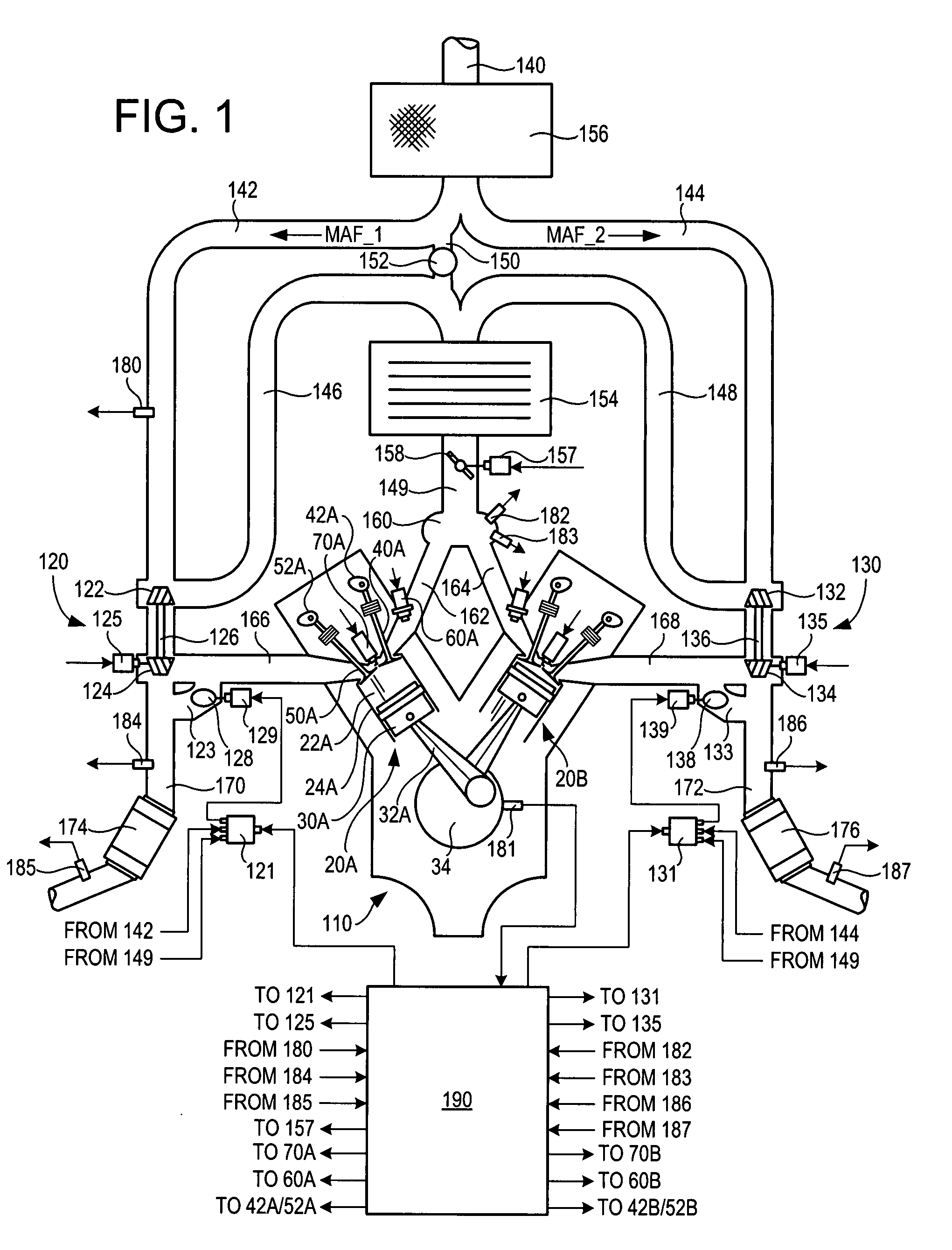
[0009]FIG. 1 shows a schematic depiction of an example engine system 100 including a multi-cylinder internal combustion engine 110 and twin turbochargers 120 and 130. As one non-limiting example, engine system 100 can be included as part of a propulsion system for a passenger vehicle. Engine system 100 can receive intake air via intake passage 140. Intake passage 140 can include an air filter 156. At least a portion of the intake air (MAF_1) can be directed to a compression device or compressor 122 of turbocharger 120 via a first branch of the intake passage 140 as indicated at 142 and at least a portion of the intake air (MAF_2) can be directed to a compressor 132 of turbocharger 130 via a second branch of the intake passage 140 as indicated at 144.

[0010]A first portion of the total intake air (MAF_1) can be compressed via compressor 122 where it may be supplied to intake manifold 160 via intake air passage 146. Thus, intake passages 142 and 146 form a first branch of the engine's ...


PUM


Abstract

As one example, a method of operating an engine system including a first air intake passage branch including a first compression device and a second air intake passage branch including a second compression device, wherein each of the first branch and the second branch are fluidly coupled to at least a combustion chamber the engine via a common intake passage, a first sensor arranged along the first branch and at least a second sensor arranged along the common intake passage, wherein the first sensor is a mass airflow sensor and wherein the second branch does not include a mass airflow sensor. The method comprises increasing the mass airflow through the first branch relative to the mass airflow through the second branch when an amount of decrease in the mass airflow through the first branch is more than half an amount of a corresponding decrease in the combined mass airflow.

Description

BACKGROUND AND SUMMARY [0001]Some internal combustion engines utilize boosting devices such as turbochargers to increase the mass airflow through the engine, thereby enabling an increase of the work output of the engine. As one example, an engine may utilize twin turbochargers in separate parallel branches of the engine's air intake system to provide increased boost to the engine. One issue with twin turbocharged engines is that the amount of airflow provided by each of the turbochargers may become unbalanced. For example, degradation or failure of a turbocharger or other component of the exhaust system or variations in engine system components may cause one of the turbochargers to provide a larger portion of the total airflow to the engine than the other turbocharger. Thus, under these conditions, the engine system may generate noise and vibration harshness (NVH), experience reduced fuel efficiency, and / or the lower airflow turbocharger may experience compressor surge and may be da...

Claims


Application Information

Patent Timeline
IPC IPC(8): F02D23/00G01P5/00F02B33/40G01M99/00
CPCF02B37/007Y02T10/144F02D23/02F02D41/0007F02D41/18F02D41/221F02D41/222F02D2200/0402F02D2200/0404F02D2200/0406F02M35/10157F02M35/10216F02M35/1038F02M35/10386F02M35/116F02B37/127F02B37/162Y02T10/12
Inventor FARMER, DAVID GEORGE
Owner FORD GLOBAL TECH LLC
Why Eureka
Try Eureka