
Cavitating core

a cavity core and core technology, applied in the field of ammunition for missile weapons and firearms, can solve the problems of oversized cavity cores, lateral surface tumble, and significant angular oscillation, and achieve the effect of increasing the effectiveness of underwater targets hitting

Active Publication Date: 2009-03-12
DSG TECH
View PDF2 Cites 14 Cited by
  • Summary
  • Abstract
  • Description
  • Claims
  • Application Information

AI Technical Summary

Benefits of technology

[0024]The purpose of the given invention is to increase the effectiveness of underwater targets hitting in the course of firing from firearms and missile weapons in the air and in the water.
[0034]Moreover, the cavitating core may be made of easily deformable material.
[0035]Moreover, the cavitating core may be made of easily deformable material with inner filling of high-density material.
[0037]The presented system of invention features allows us, within overall dimensions of conventional ammunition, to design cavitating cores having an increased range of underwater targets hitting in the course of firing in the air and in the water due to an optimal matching to the cavity contour, a reduced cavitation drag and scattering along the underwater section of trajectory.
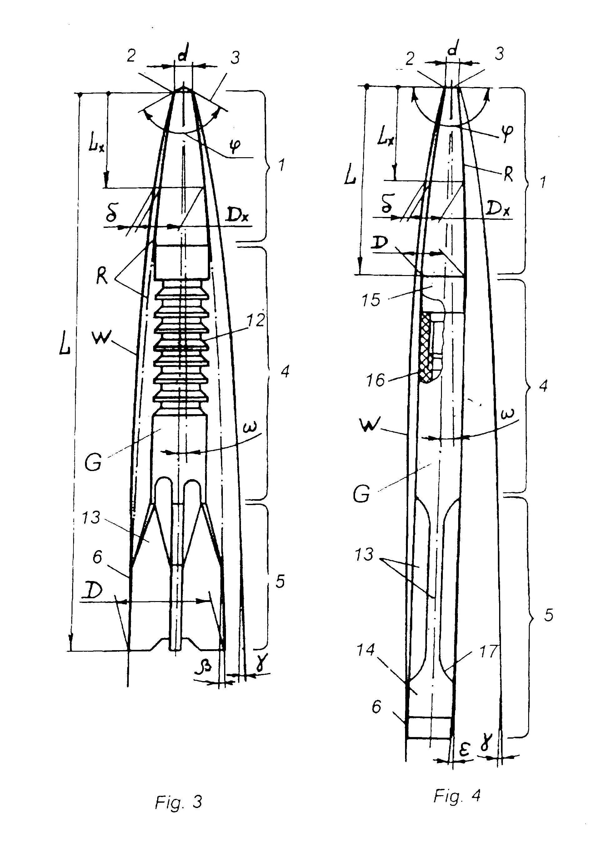
[0038]Dimensions of cavitating cores for the core length up to 6 calibers allow achieving spin-stabilization in the air and for the core length more than 6 calibers—to stabilize it with tail empennage.
[0043]The area of the gliding surface is determined in accordance with inertial parameters of the core. The understated gliding area increases the depth of inertial washing, while the overstated gliding area increases the gliding drag, both resulting in the growth of scattering along the underwater section of trajectory.

Problems solved by technology

When the central or the head part is washed in the cavity, the core loses its stability, tumbles and slows down by the lateral surface.
The disadvantage of that cavitating core with the length of more than 21 calibers lies in its geometry, as for its correspondence to the cavity contour, the cavitating edge diameter should be increased; that results in the formation of a cavity with an oversized volume, and an extended gap between the gliding surface and the cavity contour promotes significant angular oscillations and deep inertial washing of narrow blades of the tail empennage.
The above mentioned disadvantages result in the growth of scattering along the underwater trajectory and in the reduction of underwater targets hitting range.
The disadvantage of this known design lies in the fact that the cavitating core contour is significantly understated relative to the cavity contour; that reduces the mass and strength of the core.
A sharp edge on the gliding surface of empennage blades is subjected to deep washing due to its small area, and that results in the increased gliding drag.
The above mentioned disadvantages result in the growth of scattering along the underwater trajectory and in the reduction of underwater targets hitting range.
The disadvantage of this known design lies in the fact that the contour of three conjugated truncated cones cannot correspond to the cavity outline exact approximation, so the cavitating core geometry is not optimal, and the cavitating core mass is always understated, hence underwater targets hitting range is also reduced.
Besides, this cavitating core design cannot be used without a discarding sabot for shooting from arbalests and harpoon gulls, as well as from firearms.

Method used


Image

  • Cavitating core
  • Cavitating core
  • Cavitating core

Examples


Embodiment Construction

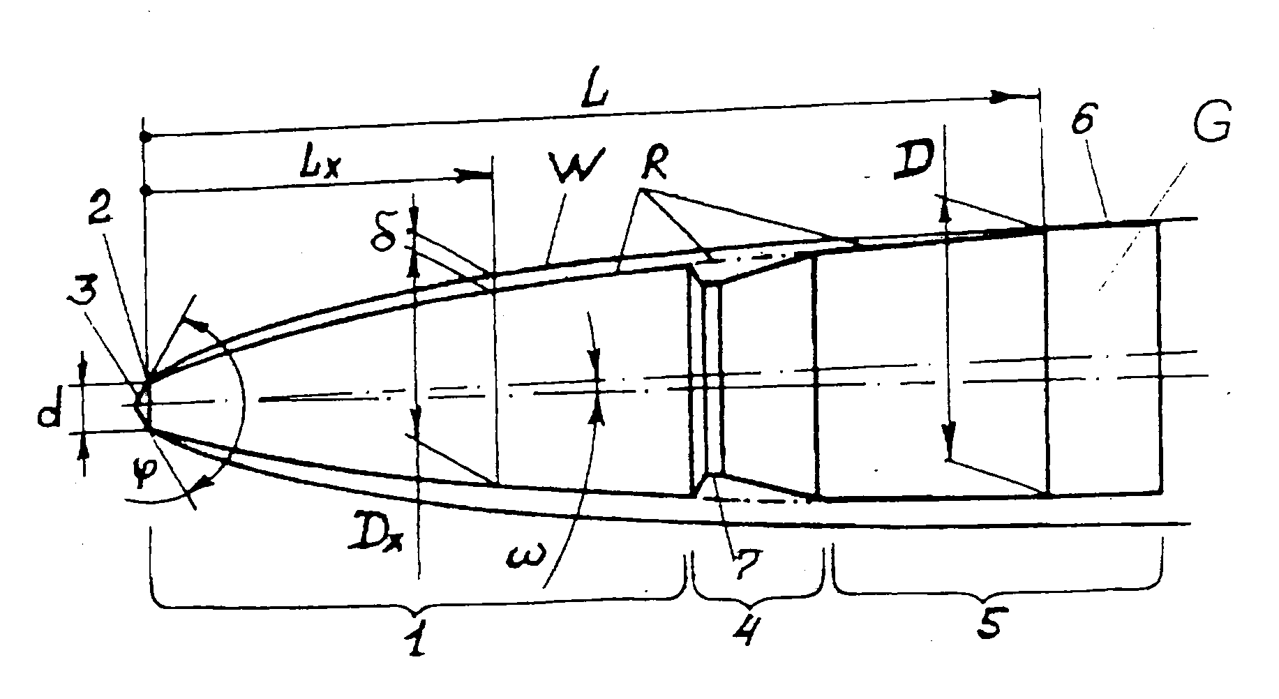
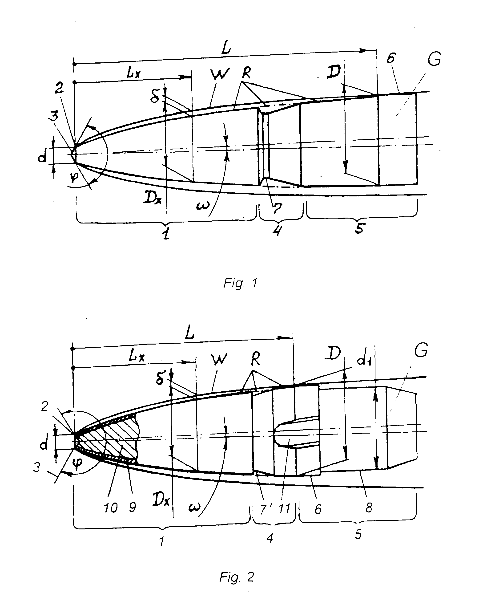
[0050]The cavitating core G consists of a head part 1 conjugated along the cavitating edge 2 having the diameter d with a secant nose surface 3, a central part 4, and an aft part 5 with a cylindrical gliding surface 6. The core caliber D is less than the barrel bore inner diameter measured at rifling fields. To prevent deformation of the conical nose surface 3 its top is rounded. For fixation in a discarding sabot the central part 4 has a groove 7.

[0051]The current diameter Dx of the cavitating core enveloping contour on the current length Lx from the cavitating edge 2 to the caliber D on the length L (excluding groove 7) coincides with the enveloping contour R that corresponds to the function:

[0052]Dx=d×[1+(Lx / d)×(2×sin φ / π)1 / N]N, where: d=1.75 mm, φ=90°, N=0.50.

[0053]The cavitating core contour R and the cavity contour W match in such a way that in the cavity the core rotary angle ω makes up less than 1.8°, and between the contour W and the core contour R there retains a gap δ of ...


PUM


Abstract

The invention relates to ammunition for missile weapon and firearm. The cavitating core of the invention comprises a head part conjugated with a secant nose surface along the cavitating edge, a central part, and an aft part with a gliding surface, wherein the caliber of the core is defined by the maximum diameter of the circle describing the core cross-section. The contour line enveloping the cross-sections from the cavitating edge to the core caliber in the plane of the core axial longitudinal section is limited by the dependence:Dx=d×[1+(Lx / d)×(2×sin φ / π)1 / N]N, whereDx—is the current diameter of the core enveloping contour R, mm;d—is the cavitating edge diameter, mm;Lx—is the current distance from the cavitating edge to the core caliber, mm;φ=60° . . . 270°—is the apex angle of the tangents to the secant nose surface at the points of its conjugation with the cavitating edge measured from the side of the head part;N=(2π / φ)0.4 . . . (2π / φ)0.2—is the core volume factor, wherein the core caliber is equal to the current diameter of the core enveloping contour Dx.As a result the invention makes it possible to increase the effective distance for hitting underwater targets when shooting from the air to the water and / or during underwater shooting using arbalests, harpoon guns, artillery, small and sporting-and-hunting weapons.

Description

FIELD OF THE INVENTION[0001]This invention relates to ammunition for missile weapon and firearm and can be used in the design of harpoon arrows for arbalests and harpoon guns, as well as in the design of bullets for small arms, artillery and sporting-and-hunting guns used for firing under the water, from the air into the water, in the air and from the water into the air. Possibility of shooting in the water is defined for every weapon system individually.BACKGROUND ART[0002]Wide interest in underwater sports stimulates creation of cavitating cores for sport shooting at underwater marks and for underwater hunting with arbalests, harpoon guns and firearms.[0003]The need in creating cavitating cores arises from the fact that harpoon arrows for arbalests and harpoon guns slow down in the water and quickly stop due to the viscous fluid hydrodynamic drag, and available bullets intended for firing in the air loose their stability after entering the water and come to stop at the range of 0....

Claims


Application Information

Patent Timeline
Patent Type & Authority Applications(United States)
IPC IPC(8): F42B10/42
CPCF42B6/08F42B15/22F42B10/46F42B10/42
Inventor POLOVNEV, ANDREY ALBERTOVICHKHASIAKHMETOV, VLADIMIR SHAYMUKHAMETOVICH
Owner DSG TECH
Learn More