
Automatic panel cutting and seaming system

a cutting and seaming system technology, applied in the field of sewing systems and methods, can solve the problems of increasing the cost and slow production of such articles, limiting the type and number of sewing operations that can be performed, and requiring a large amount of sewing

Active Publication Date: 2009-03-12
ATLANTA ATTACHMENT
View PDF33 Cites 17 Cited by
  • Summary
  • Abstract
  • Description
  • Claims
  • Application Information

AI Technical Summary

Benefits of technology

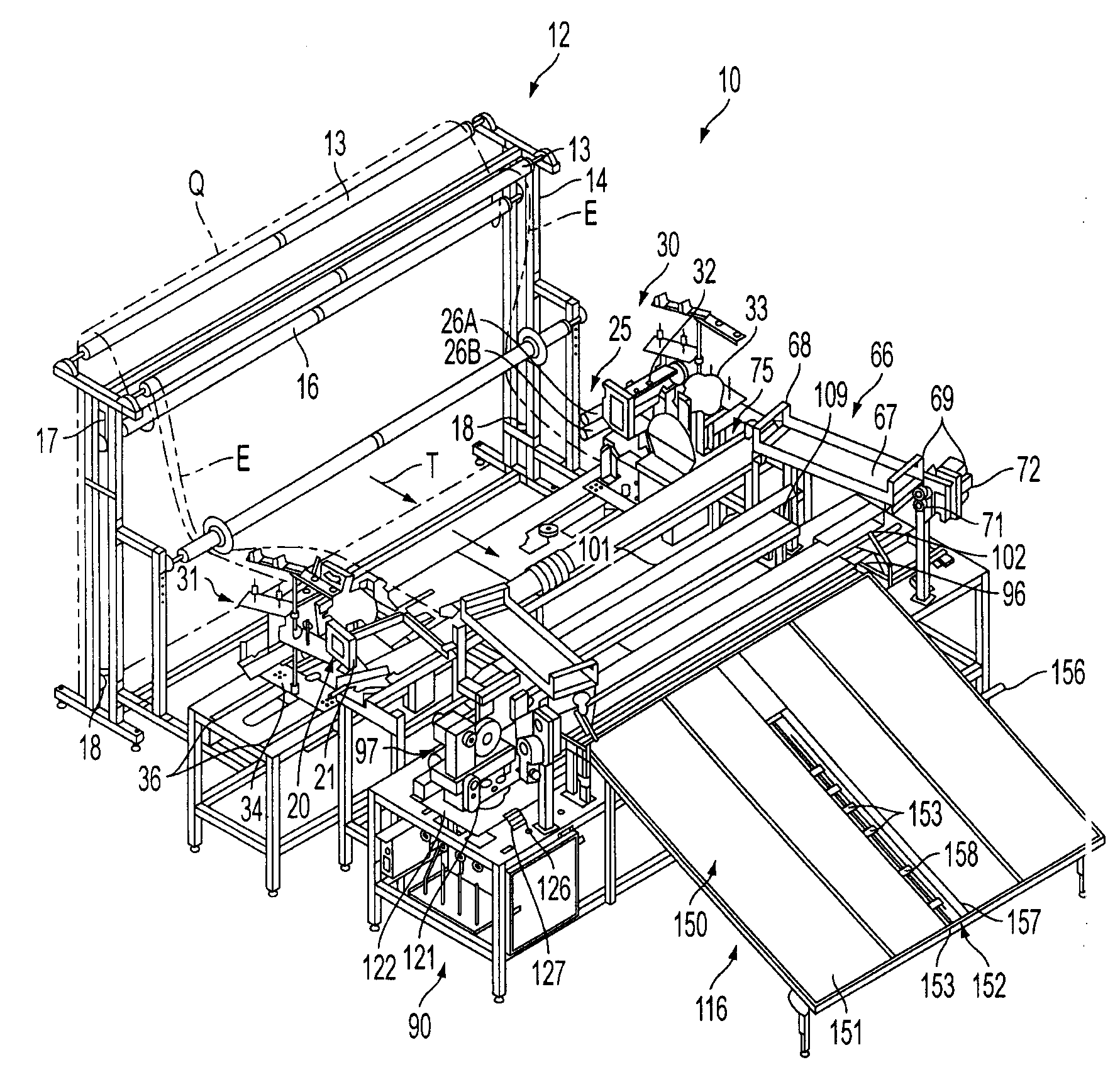
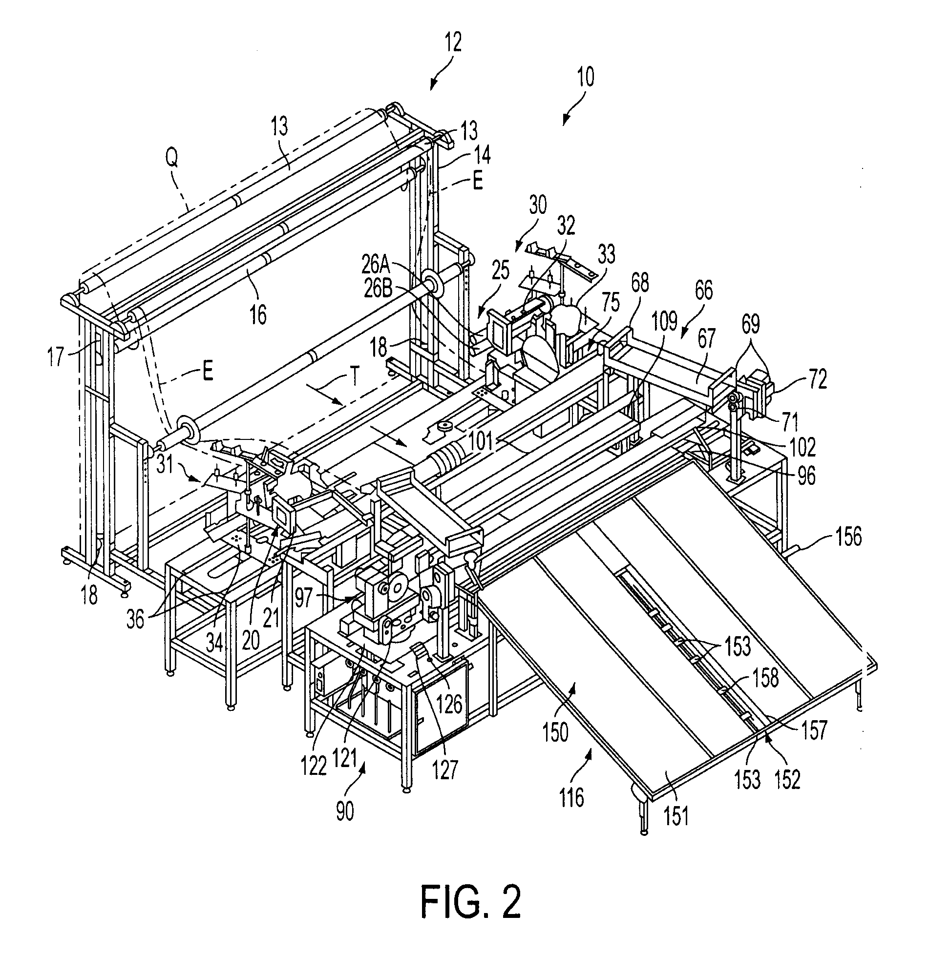
[0008]After a sufficient amount of quilted panel material has been fed into the automatic panel cutting and sewing system for a given panel size, as detected by sensors mounted along an output or feed table, a cross-cut sewing assembly generally will be activated. The cross-cut sewing assembly includes a clamp assembly that engages and holds the material taut, a collapsible bridge, and a multi-needle cross-cut sewing head that will move across the width of the panel to cut and sew the trailing edge of the finished panel. The multi-needle cross-cut sewing head is multi-directional and typically will include one-two pairs of spaced needles, one-two or more top belt feed drive mechanisms, and a cutting blade or trimmer approximately centrally located between the needles. As the multi-needle cross-cut sewing head is moved across the width of the quilted material, it cuts the quilted panel material, while at the same time the sewing needles thereof sew seams or lines of stitching adjacent the cut upstream and downstream side edges of the quilted panel material, thus forming seamed trailing and leading edges of the cut panel and the next panel to be formed. Once the cross-cut sewing head has moved across the quilted material, and cut the panel therefrom, it generally is pivoted approximately 180° to enable it to cut and sew the next panel as it moves back across the path of travel of the quilted material, without having to be reset or moved back across the path of travel of the quilted material to a start position on one side of the cross-cut sewing assembly. Sensors control the lateral movement of the cross-cut sewing head.
[0009]The cross-cut sewing head also can be positioned at various positions upstream or downstream from the left- and right-hand side-edge sewing machines so as to cut a panel of a desired length either before or after the side edges of the panels are cut and seamed / sewn. In one embodiment, the cross-cut sewing head can be positioned upstream from the right- and left-hand side edge sewing machines so as to cut and seam the longitudinal upstream and downstream edges of the panels, thus forming the panels of a desired length, prior to the panels being engaged by the side edge sewing machines. Such an arrangement can enable the shorter transitional waste, since the panel is already cut to a desired length, and substantially any width panel can be run at almost any time because of the side seaming / cutting locations. Alternatively, the cross-cut sewing machine can be positioned downstream from the side edge sewing machines so as to cut and sew the longitudinal edges of the panels after their side edges have already been cut and seamed. With such an arrangement, there can be a reduction in trim waste from the longitudinal, leading and trailing or upstream and downstream edges of the panels, although there may be additional transitional waste when running different width panels back to back.

Problems solved by technology

In the manufacture of textiles, and in particular bedding, the sewing operations traditionally have been extremely labor intensive, manual operations that generally require highly skilled workers for cutting, sewing, finishing and assembling textile articles such as mattresses, foundation sets or other, similar articles.
The more labor intensive the sewing operation and the greater the skill required of the operator(s) to cut, finish and assemble the components thereof, the greater the cost and the slower the production of such articles.
The drawback of such automated equipment, however, is that it typically has been limited in the type and number of sewing operations that can be performed.
Such separation of the sewing or finishing stations is often due to the limited amount of space in the plant and ultimately leads to manufacturing inefficiencies.

Method used


Image

  • Automatic panel cutting and seaming system
  • Automatic panel cutting and seaming system
  • Automatic panel cutting and seaming system

Examples


Embodiment Construction

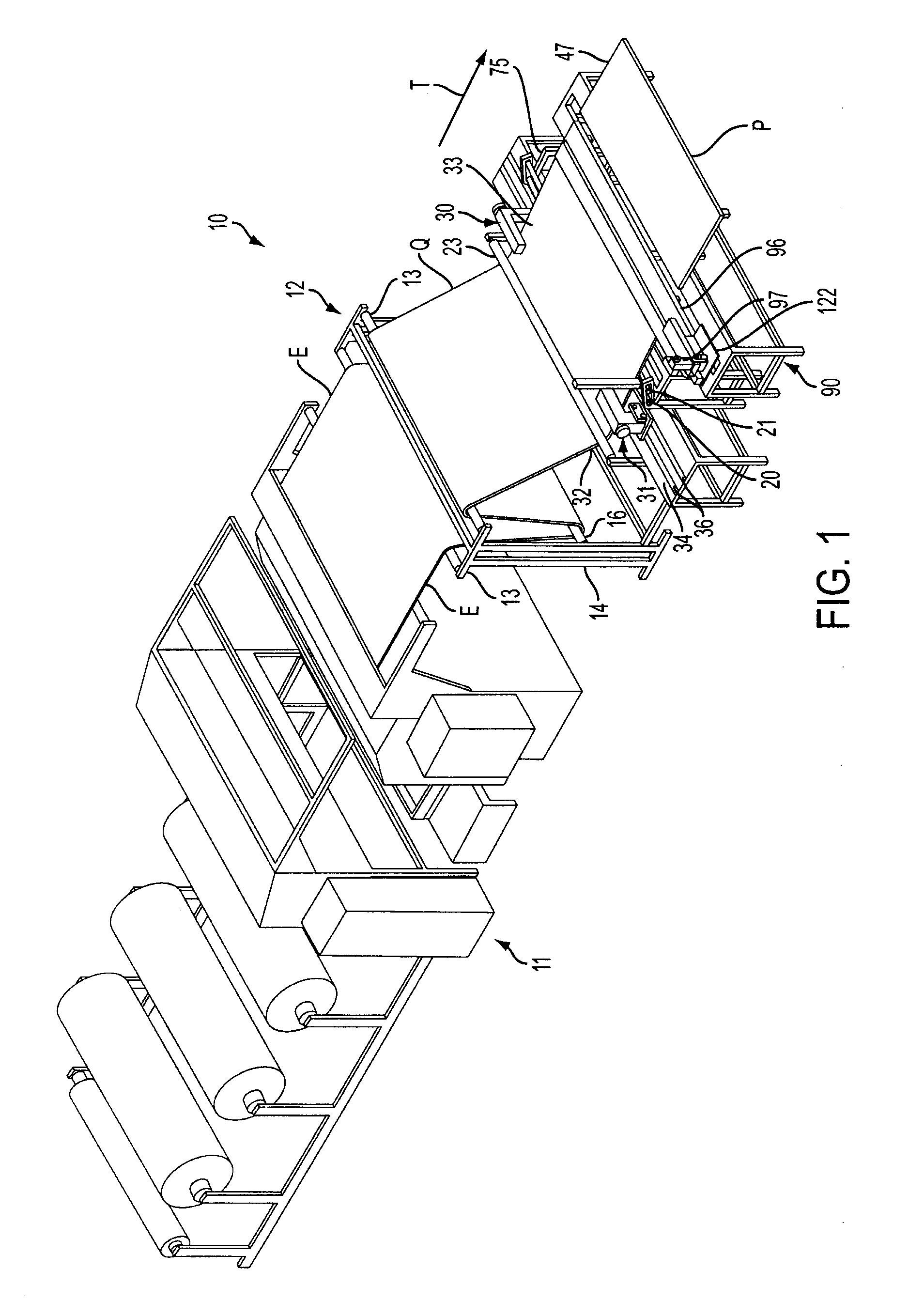
[0020]Referring now to the drawings in which like numerals indicate like parts throughout the several views, FIGS. 1-8 illustrate an automatic panel cutting and seaming system or station 10 for cutting and seaming the side and leading and trailing edges of a fabric material, such as quilted material Q shown in FIG. 1, for forming fabric panels, such as a mattress panel P, of desired sizes, such as for use in forming king size, queen size, double, twin, etc., size mattresses, or other similar products. FIGS. 9A and 9B schematically illustrate the operation of alternative embodiments of the automatic panel cutting and seaming system for forming panels of varying desired sizes.

[0021]As generally illustrated in FIG. 1, the quilted material Q can be received from an upstream source, such as a quilting machine 11, such as described and claimed in U.S. patent application Ser. No. 11 / 677,778, the disclosure of which is incorporated herein in its entirety, in which a fabric material is sewn ...


PUM


Abstract

An automatic panel cutting and edge seaming system includes a series of side edge cutting and seaming assemblies that receive a fabric material and trim and sew seams along the side edges of the fabric material to form a desired width panel. Puller rolls pull the material through the side edge cutting and seaming assemblies and feed the trimmed and seamed fabric material to a cross-cut sewing assembly. After a sufficient length of fabric material has been fed to form a desired size panel, the cross-cut sewing assembly is engaged to cut and seam the end of the panel.

Description

CROSS REFERENCE TO RELATED APPLICATIONS[0001]This application claims the benefit of U.S. Provisional Application No. 60 / 971,018, entitled AUTOMATIC PANEL CUTTING AND SEAMING SYSTEM, filed Sep. 10, 2007, which application being incorporated herein by reference in its entirety.FIELD OF THE INVENTION[0002]The present invention generally relates to sewing systems and methods for forming mattresses, foundation sets and other, similar articles, and in particular, to a method of forming and seaming the longitudinal and lateral edges of a panel formed from a quilted material for use in forming the top panels of a mattress or other bedding component.BACKGROUND OF THE INVENTION[0003]In the manufacture of textiles, and in particular bedding, the sewing operations traditionally have been extremely labor intensive, manual operations that generally require highly skilled workers for cutting, sewing, finishing and assembling textile articles such as mattresses, foundation sets or other, similar ar...

Claims


Application Information

Patent Timeline
IPC IPC(8): D05B37/08D05B11/00
CPCD05B35/08D05B11/00Y10S83/937Y10T83/9403
Inventor OXLEY, WARRENCHAMLEE, JOHN S.NGUYEN, VAN H.MURPHY, DANNY V.
Owner ATLANTA ATTACHMENT
Learn More