Electromagnetic Actuator and Fuel Injection Device

Inactive Publication Date: 2009-03-12
MIKUNI CORP
View PDF5 Cites 7 Cited by
  • Summary
  • Abstract
  • Description
  • Claims
  • Application Information

AI Technical Summary

Benefits of technology

[0033]The electromagnetic actuator and the fuel injection device having the above constitutions allow thus, for instance, increasing and flattening the electromagnetic force (drive force or thrust), enhancing responsiveness, enhancing p

Problems solved by technology

Such a fuel injection device is also problematic in that, since the inner yoke comprises two parts, component management and assembly operations, among others, become more burdensome, with increased associated costs.
Such a fuel injection device is also problematic in that, since the return channel is provided between the inner yoke and the coil, and since the outer yoke and the end yoke extend beyond the pressure-feeding chamber up to the vicinity of the injection nozzle, the

Method used


Image

  • Electromagnetic Actuator and Fuel Injection Device
  • Electromagnetic Actuator and Fuel Injection Device
  • Electromagnetic Actuator and Fuel Injection Device

Examples


Embodiment Construction

[0095]Embodiments of the present invention are explained below with reference to accompanying drawings.

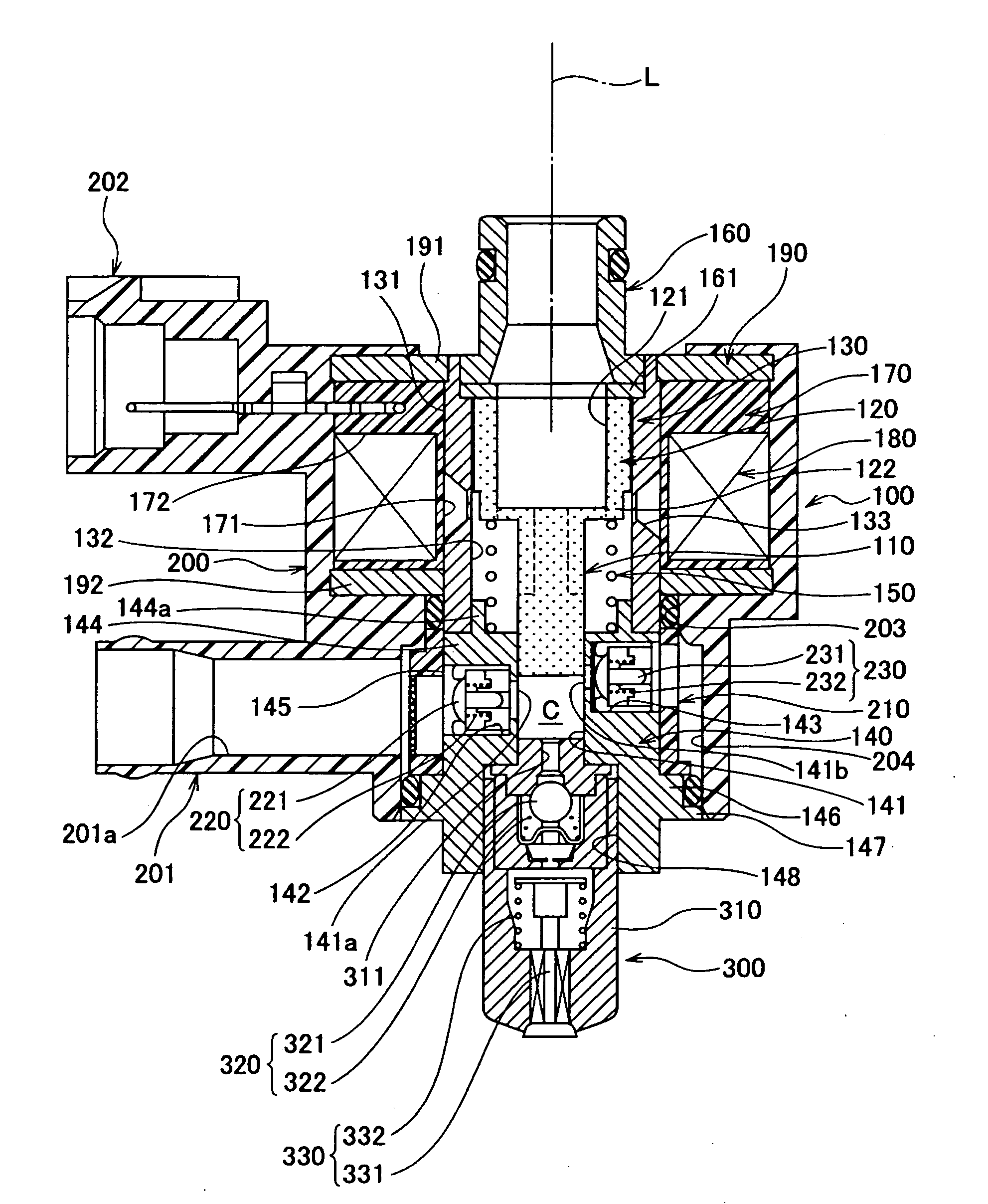
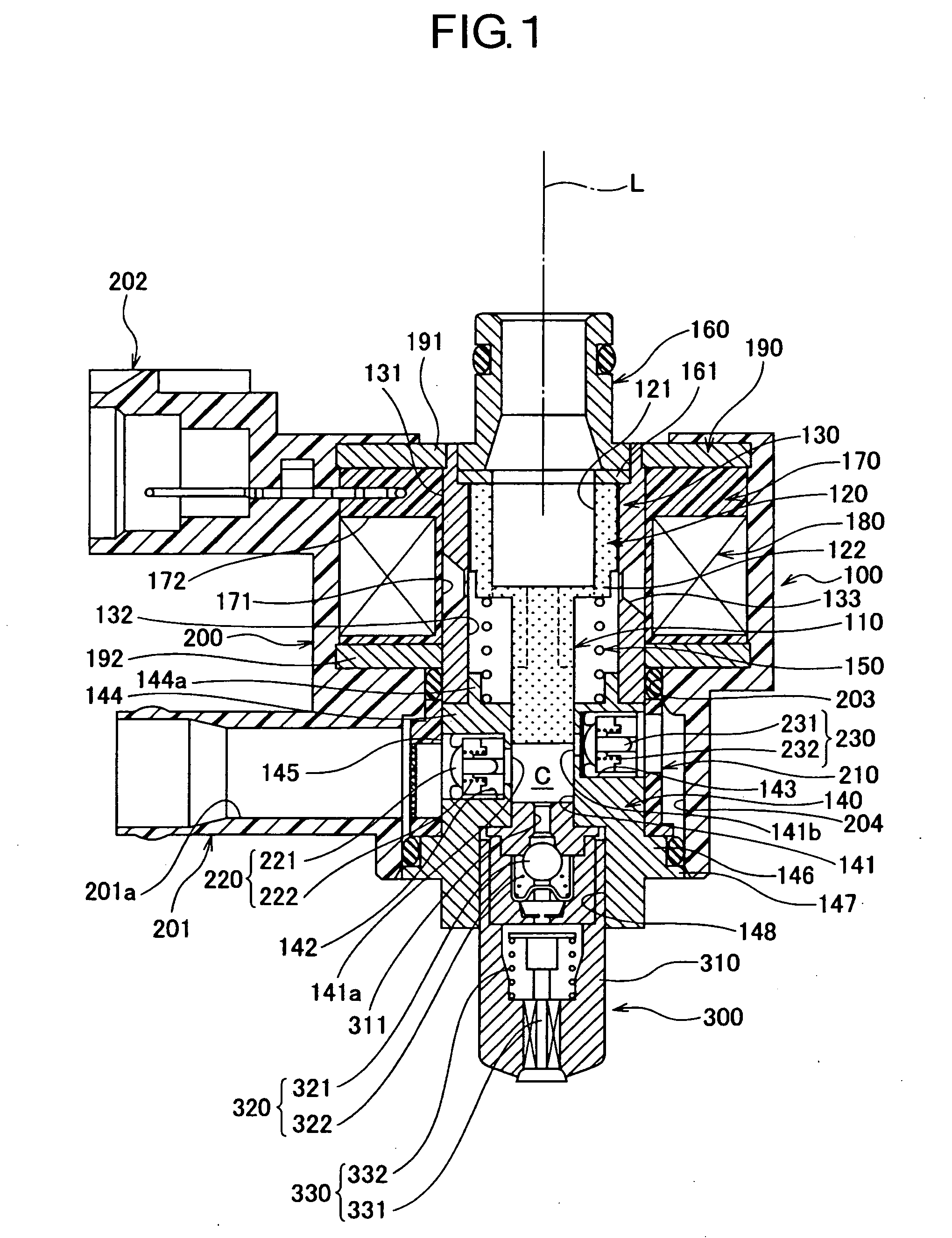
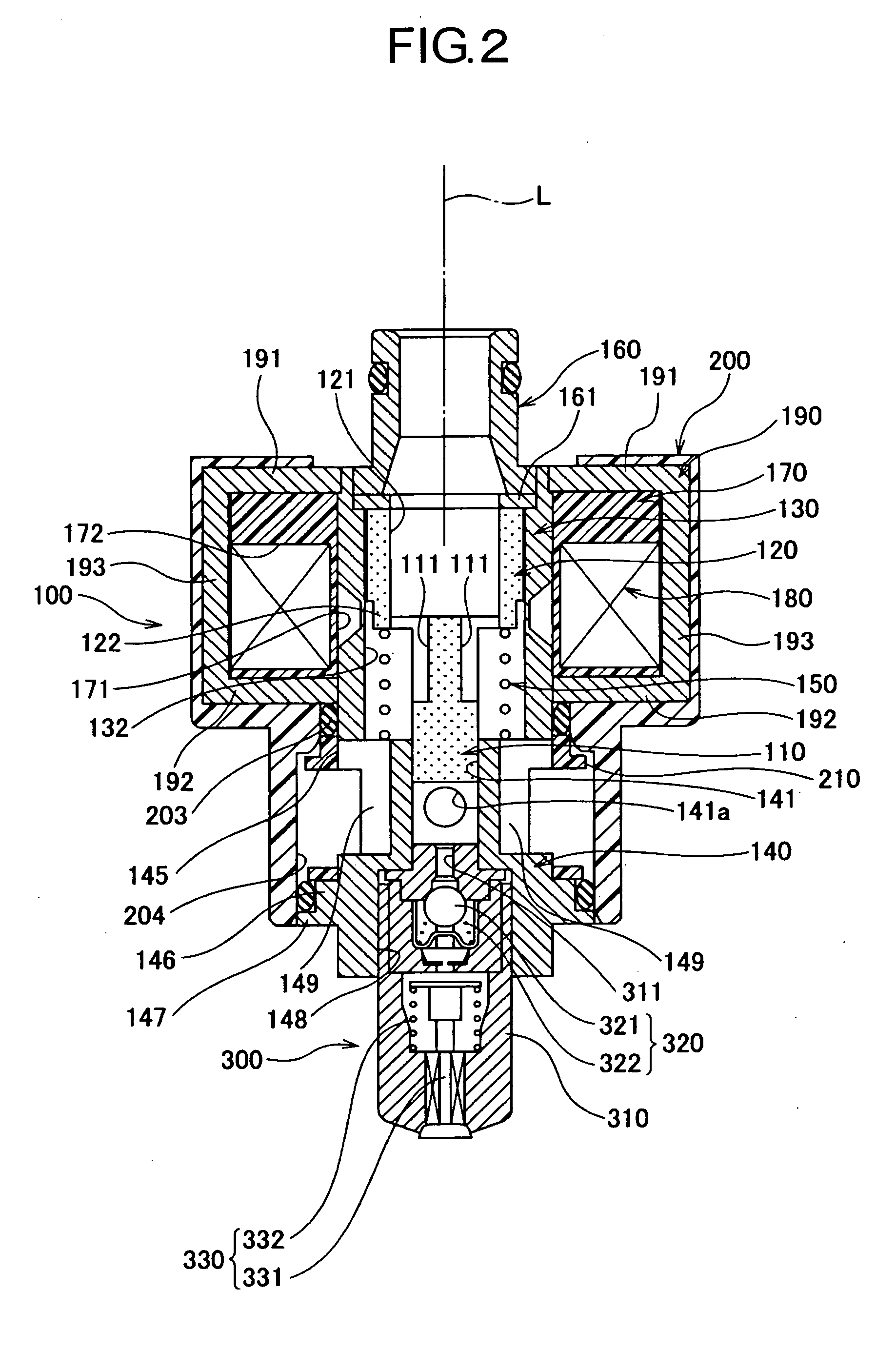
[0096]FIGS. 1 to 5 are diagrams illustrating an embodiment of a fuel injection device having as a driving source an electromagnetic actuator according to the present invention; FIGS. 1 and 2 are vertical cross-sectional diagrams of a device; FIG. 3 is a side view diagram and a vertical cross section diagram illustrating a tubular yoke; FIG. 4 is a plan view diagram, a side view diagram and a vertical cross-section diagram illustrating an armature and a plunger; and FIG. 5 is a schematic diagram illustrating the flow of magnetic field lines of the electromagnetic actuator.

[0097]As illustrated in FIGS. 1 and 2, the fuel injection device comprises, for instance, a plunger pump 100, as a drive source of an electromagnetic actuator, for pressure-feeding fuel, and an injection nozzle 300 for injecting fuel pressurized at or above a predetermined pressure.

[0098]As illustrated in FIGS. 1 a...


PUM


Abstract

[Problem] To reduce the size, lower the cost and increase and flatten the thrust of an electromagnetic actuator in which a plunger moves reciprocally.
[Solution] The electromagnetic actuator comprises a yoke 130, a coil 180 arranged around the yoke, an armature 120 slidably arranged inside the yoke and integrally formed with a plunger 110, and a return spring 150 for returning the armature to a rest position, wherein the yoke 130 has, in a predetermined position on the axial direction L, a thickness-reduced annular gap groove 133 over part of an outer peripheral face 131, the thickness-reduced portion having a trapezoidal cross section widening outwards. Such a constitution allows shortening the magnetic path, allows increasing and flattening the electromagnetic force (thrust) generated for the displacement of the armature, allows increasing the acceleration (responsiveness) of the armature, and allows, for instance, reducing the parts count, simplifying assembly operations, and achieving cost reductions, while requiring no high-precision control of assembly positions.

Description

TECHNICAL FIELD[0001]The present invention relates to an electromagnetic actuator comprising a reciprocating plunger, and to a fuel injection device which uses this electromagnetic actuator as a drive source and which injects fuel into the intake channel of an engine, and more particularly to an electromagnetic actuator and a fuel injection device used in a small engine installed in a two-wheel vehicle or the like.BACKGROUND ART[0002]Known electronic-control type fuel injection devices installed in two-wheel vehicles and the like include fuel injection devices arranged in an intake pipe or the like at a position lower than a fuel tank, wherein the fuel injection device injects, through a fuel injection nozzle, fuel led out of the fuel tank and pressure-fed by an electromagnetically driven plunger pump, the excess fuel and the generated vapor being returned to the fuel tank via a return pipe.[0003]Such a fuel injection device (see, for instance, Patent reference 1 and Patent referenc...

Claims


Application Information

Patent Timeline
IPC IPC(8): F02M51/06H02K33/02F16K31/06
CPCF02M51/04H02K33/04F02M57/027
Inventor MIZUI, HIROSHIITABASHI, YUSUKEKARASAWA, TOSHIO
Owner MIKUNI CORP
Why Eureka
Try Eureka