Light- Emitting Diode Lighting Apparatus and Vehicle Light Lighting Apparatus Using the Same

a technology of light-emitting diodes and lighting apparatus, which is applied in the direction of electric variable regulation, process and machine control, instruments, etc., can solve the problems of intermittent (blinking) lighting that causes the stroboscopic phenomenon, the difficulty of constant current flowing through the leds, and the undesirable effect of intermittent lighting driving the vehicle, etc., to achieve simple circuit configuration and reduce the size and price of the apparatus

Active Publication Date: 2009-03-12
MITSUBISHI ELECTRIC CORP
View PDF6 Cites 36 Cited by
  • Summary
  • Abstract
  • Description
  • Claims
  • Application Information

AI Technical Summary

Benefits of technology

[0020]As described above, according to the present invention, the apparatus is configured in such a manner that the plurality of boosting circuits for boosting the voltage of the DC-power supply are connected in parallel, output the current alternately, and supply the current to the LEDs. This makes it possible to eliminate the period in which the current flowing through the plurality of LEDs connected in series becomes zero. Thus, it can prevent the light

Problems solved by technology

As described above, as for the configuration of connecting the smoothing capacitor in parallel with the LEDs having the constant voltage characteristics, although it is easy for the boosting circuit to make the terminal voltage to be applied to the LEDs constant, it is difficult to make the current flowing through the LEDs constant.
Thus, the first conventional example has a problem in that the current flowing through the LEDs is intermittent, and hence the light emitted by the LEDs is also intermittent.
However, if it is a moving object, it is perceived as if it were at rest for a moment because of a stroboscopic phe

Method used


Image

  • Light- Emitting Diode Lighting Apparatus and Vehicle Light Lighting Apparatus Using the Same
  • Light- Emitting Diode Lighting Apparatus and Vehicle Light Lighting Apparatus Using the Same
  • Light- Emitting Diode Lighting Apparatus and Vehicle Light Lighting Apparatus Using the Same

Examples


embodiment 1

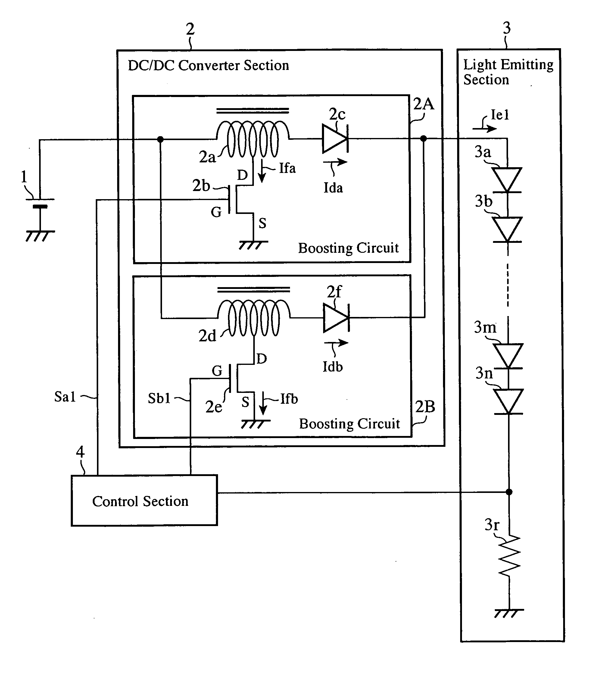
[0031]FIG. 1 is a diagram showing a configuration of the light-emitting diode lighting apparatus of an embodiment 1 in accordance with the present invention.

[0032]In FIG. 1, the light-emitting diode lighting apparatus is constructed from four main divisions of a DC power supply 1, a DC / DC converter section 2, a light emitting section 3 and a control section 4.

[0033]In the configuration, the DC power supply 1 is a battery loaded on a vehicle, for example.

[0034]The DC / DC converter section 2 comprises a plurality of boosting circuits connected in parallel for boosting the voltage of the DC power supply 1, and supplies a current to light-emitting diodes in the light emitting section 3. The DC / DC converter section 2 as shown in FIG. 1 comprises two flyback type circuits, a boosting circuit 2A and a boosting circuit 2B, connected in parallel.

[0035]The two boosting circuits 2A and 2B have the same configuration: the first boosting circuit 2A is composed of a single-winding (coil) boosting ...

embodiment 2

[0056]FIG. 4 is a diagram showing a configuration of the light-emitting diode lighting apparatus of an embodiment 2 in accordance with the present invention. In FIG. 4, the same components as those of FIG. 1 are designated by the same reference symbols, and their description will be omitted here.

[0057]In FIG. 4, the configuration of FIG. 4 differs from that of FIG. 1 in the configuration of the DC / DC converter section 11 for boosting the voltage of the DC power supply 1. The DC / DC converter section 2 of FIG. 1 is constructed by connecting the two flyback type boosting circuits in parallel. In contrast with this, the DC / DC converter section 11 of FIG. 4 is constructed by connecting two charge pump type boosting circuits 11A and 11B in parallel. The charge pump type boosting circuit is a circuit for boosting by superimposing the voltage charged in the capacitor on the power supply voltage, and has a feature of not employing the transformers 2a and 2d as shown in FIG. 1.

[0058]The first...

embodiment 3

[0074]FIG. 5 is a diagram showing a configuration of the light-emitting diode lighting apparatus of an embodiment 3 in accordance with the present invention. In FIG. 5, the same components as those of FIG. 1 are designated by the same reference symbols, and their description will be omitted here.

[0075]In FIG. 5, the configuration of FIG. 5, which includes a DC / DC converter section 21 having two resonance type boosting circuits 21A and 21B similar to their counterparts of FIG. 1 connected in parallel, differs from the configuration of FIG. 1 in the following: it has a resonance capacitor 2g between the connection point of the tap of the transformer 2a and the drain (D) of the switching device 2b and the ground; has a resonance capacitor 2h in the same way between the connection point of the tap of the transformer 2d and the drain (D) of the switching device 2e and the ground; and connects the individual drains (D) of the switching devices 2b and 2e to the control section 22. The rema...


PUM


Abstract

A single DC/DC converter section 2 has two circuits connected in parallel: a flyback type boosting circuit 2A and a boosting circuit 2B. The former includes a transformer 2a and a switching device 2b and the like to boost DC voltage of a DC power supply 1, and the latter includes a transformer 2d and a switching device 2e and the like to do likewise. A control section 4 carries out switching control of the switching devices 2b and 2e in such a manner that shifts from each other the phases of current Ida and current Idb to be supplied from the two boosting circuits 2A and 2B to a plurality of LED 3a and the like connected in series in a light emitting section 3.

Description

TECHNICAL FIELD[0001]The present invention relates to a light-emitting diode lighting apparatus and a vehicle light lighting apparatus using the same capable of improving the continuity of lighting of a plurality of light-emitting diodes connected in series in lighting using a boosting type direct current / direct current converter (called “DC / DC converter” from now on).BACKGROUND ART[0002]Conventional lighting apparatuses using light-emitting diodes (called “LEDs” from now on) include the following:[0003]As a first conventional example, an apparatus is known which has a plurality of LEDs connected in series, supplies the LEDs connected in series with a voltage boosted from a power supply voltage by a DC / DC converter, and causes the same current to flow through all the LEDs to light them (see Patent Document 1, for example).[0004]As a second conventional example, an apparatus is known which employs a charge pump type boosting power supply using a capacitor, and arranges a constant cur...

Claims


Application Information

Patent Timeline
IPC IPC(8): H05B37/02B60Q1/00H01L33/00
CPCH02M3/07H05B33/0815H02M3/1584H05B45/38H05B45/385
Inventor TATEISHI, NORIKAZUOHSAWA, TAKASHI
Owner MITSUBISHI ELECTRIC CORP
Why Eureka
Try Eureka