
Apparatus and system for electro magnetic field measurements and automatic analyses of phase modulated optical signals from electrooptic devices

an electrooptic device and automatic analysis technology, applied in the field of electromagnetical field sensors and automatic analysis systems, can solve the problems of inability to accurately detect the phase modulation of the optical signal, etc., to achieve the maximum responsivity of the sensor, stabilize the temperature and photo-induced signal fluctuations, and maximize the effect of sensor responsivity

Inactive Publication Date: 2009-03-12
US GOVT REPRESENTED BY SEC OF THE NAVY CHIEF OF NAVAL RES CODE OOCCIP OFFICE OF COUNSEL ONR NRL
View PDF8 Cites 19 Cited by
  • Summary
  • Abstract
  • Description
  • Claims
  • Application Information

AI Technical Summary

Benefits of technology

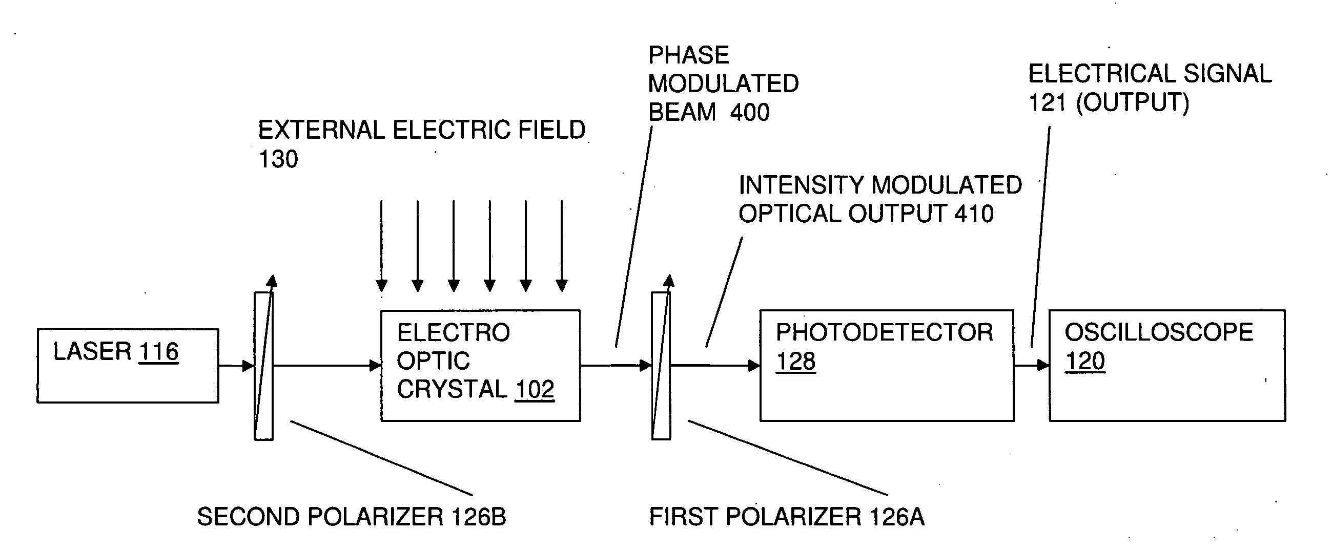
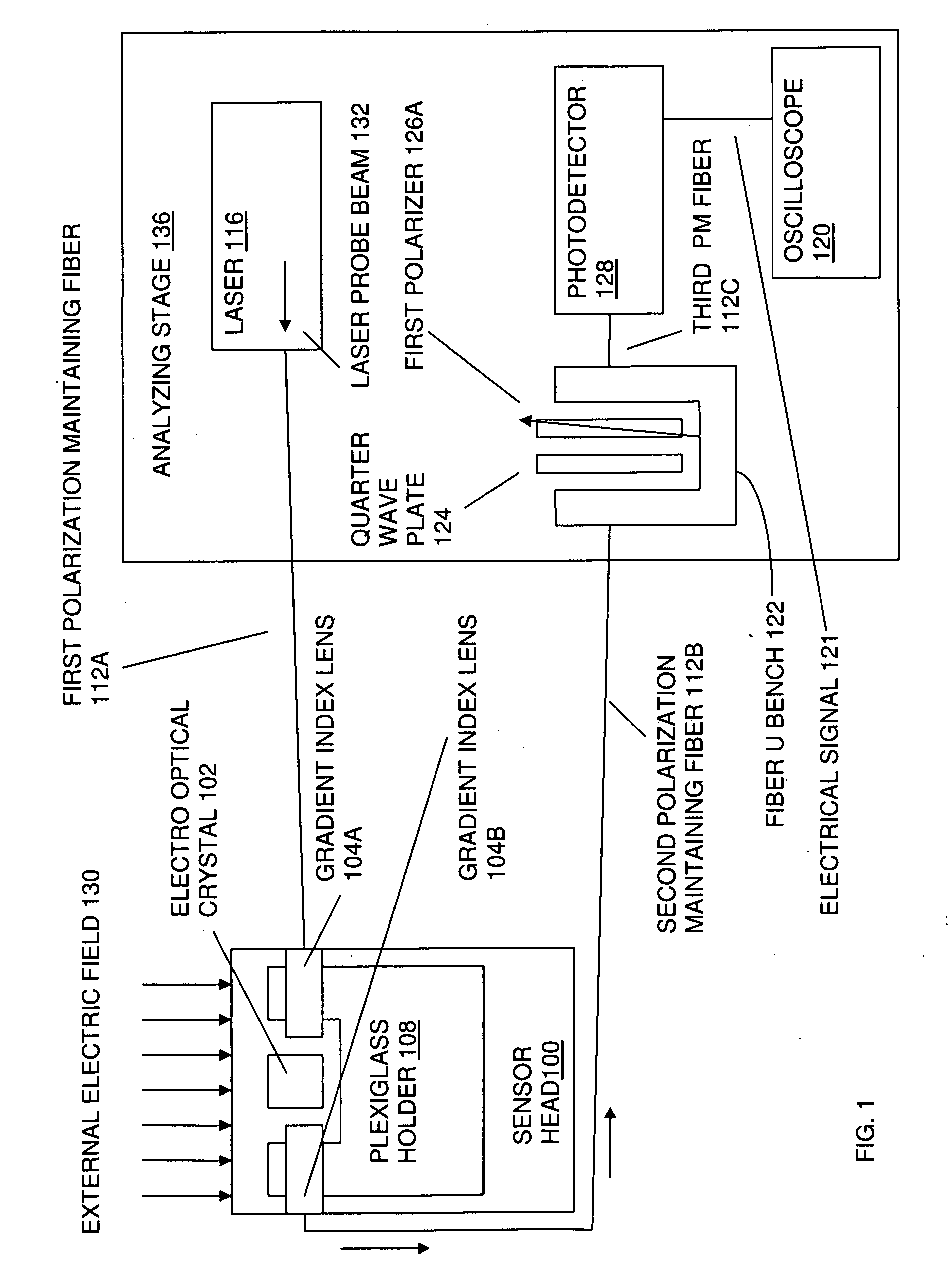
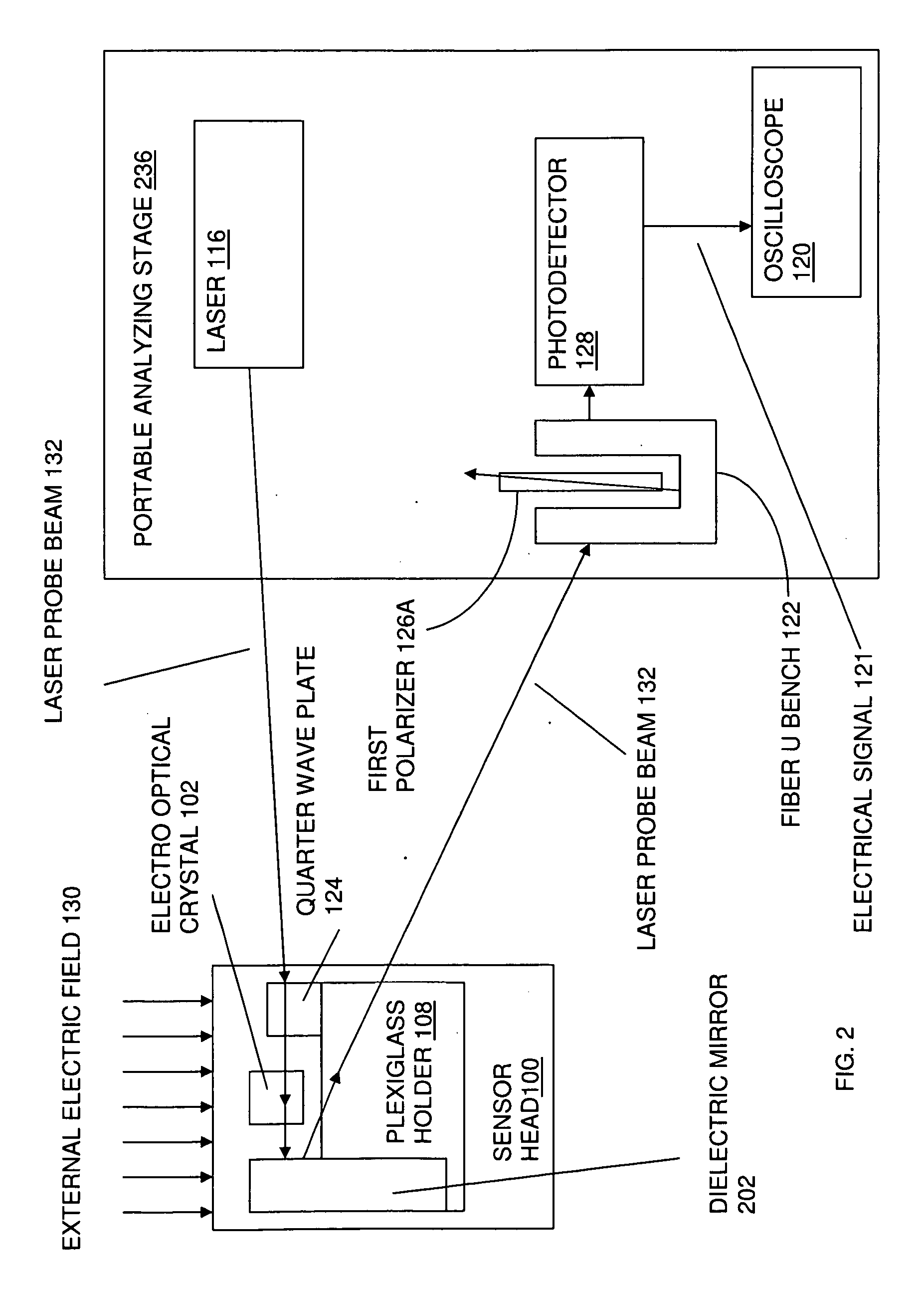
"The patent describes an apparatus for measuring external electric fields using a laser and electro optic crystal. The sensor head is optically coupled to the analyzing stage through optical fiber leads. The laser beam is transmitted from the analyzing stage to the sensor head and then returned to the analyzing stage through a polarization maintaining optical fiber. The laser beam is phase modulated by the electric field and analyzed by the electro optic crystal before being converted into an optical modulation signal by the quarter wave retardation plate and polarizer. The unique orientation of the crystal axis with respect to the fast / slow axes of the fiber optic cable and the quarter wave retardation plate ensures stable and maximum sensor responsivity regardless of fluctuations or drifts in the birefringence of the crystal. The apparatus can be used for wide bandwidth, non-perturbative measurements of external electric fields."

Problems solved by technology

Limitations and disadvantages of these conventional sensors include: (1) unacceptably large field perturbations, (2) narrow bandwidth, and (3) bulky physical size.
The large field perturbations render these sensors unable to measure true waveform of the electric and magnetic fields.
These conventional sensors have a very narrow frequency bandwidth (typically less than 1 GHz) and hence they are not suitable for wideband HPM test and evaluation.
Also, the conventional electric field sensor (D dot sensor) is large in size, and thus unable to measure detailed field patterns in small areas.
However, a major problem with electro optic field sensors is that the optical modulation signal can undergo fluctuations and drifts in its amplitude and phase, even if the applied field has a steady state amplitude and phase.
Because of these fluctuations, precise field measurements become difficult or impossible.
This instability problem is likely to be a major reason why little effort has been made to commercialize the use of electro optic field sensors in field measurement applications.
Such a technique can improve the stability of the responsivity to a certain degree; however, continuous manual adjustments are cumbersome and can not always recover the signal loss.
No device hitherto exists to eliminate these instabilities and keep the device stably operating at its peak responsivity.

Method used


Image

  • Apparatus and system for electro magnetic field measurements and automatic analyses of phase modulated optical signals from electrooptic devices
  • Apparatus and system for electro magnetic field measurements and automatic analyses of phase modulated optical signals from electrooptic devices
  • Apparatus and system for electro magnetic field measurements and automatic analyses of phase modulated optical signals from electrooptic devices

Examples


example 1

[0063]FIG. 6 and FIG. 7 illustrate the stability and maximization of modulation amplitude (V) of intensity modulated light signals, such as intensity modulated optical output 410 (see FIG. 4 and FIG. 5), from EO modulating devices. FIG. 6 and FIG. 7 compare the modulation pulse height from an EO field sensor plotted as a function of time. In FIG. 6, a traditional polarizer, such as the first polarizer 126A, (set at a fixed angle which optimized responsivity) was used in the analyzing stage, such as the analyzing stage 136. In FIG. 7, an auto analyzer, i.e., the first polarizer 126A automated in auto analyzing stage 536 (see FIG. 5) was used to analyze the laser probe beam 132. The deviations shown in FIG. 6 represent the deviations in the value of the phase factor sin φ0, as previously discussed. As demonstrated by a comparison of FIG. 6 and FIG. 7, the auto analyzer can overcome these deviations and keep the EO sensor stable and operating at its peak responsivity.


PUM


Abstract

An apparatus, for measuring an electric field while minimally perturbing the electric field being measured, includes an analyzing stage and a sensor head. The sensor head is optically coupled to the analyzing stage by a laser probe beam transmitted from the analyzing stage. The sensor head includes an electro optic crystal disposed between two gradient index lenses, where the first gradient index lens emits a laser beam transmitted from the analyzing stage to the sensor head, where the electric field is applied and where, the electro optic crystal transforms the laser beam probe into a phase modulated laser beam. The second gradient index lens transmits the phase modulated laser beam back to the analyzing stage, where polarization optics and a photodetector convert the phase modulated laser beam into an electrical signal representing field strength and phase of the electric field.

Description

CROSS REFERENCE TO RELATED APPLICATIONS[0001]The present application is a nonprovisional application of provisional application No. 60 / 970,367 under 35 USC 119(e), the entire disclosure of which is incorporated by reference herein.FIELD OF THE INVENTION[0002]The present invention is generally related to test and evaluation of high power microwave emissions and optical beam modulation devices. In particular the present invention is directed to an electromagnetic field sensor and an automatic analyzer therefor.FIELD OF THE INVENTION[0003]The present invention is generally related to test and evaluation of high power microwave emissions and optical beam modulation devices. In particular the present invention is directed to an electromagnetic field sensor and an automatic analyzer therefor.BACKGROUND OF THE INVENTION[0004]Presently D dot and B dot sensor probes are used for high power microwave (HPM) tests and evaluations, wherein a D dot sensor is a dipole antenna based device capable ...

Claims


Application Information

Patent Timeline
Patent Type & Authority Applications(United States)
IPC IPC(8): G01J4/00
CPCG01R31/308G01R29/0885
Inventor WU, DONG HOGARZARELLA, ANTHONY
Owner US GOVT REPRESENTED BY SEC OF THE NAVY CHIEF OF NAVAL RES CODE OOCCIP OFFICE OF COUNSEL ONR NRL
Learn More