
Device for transmitting and receiving DVI video over a single fiber optic interconnect

a fiber optic interconnect and video technology, applied in the direction of optical elements, electromagnetic transceivers, instruments, etc., can solve the problems of increasing the number of data required to maintain a quality image, increasing the cost and construction burden of transmitter and receiver interconnects, and prior concepts proving inadequate for efficient fiber optic interconnects. the effect of efficient us

Active Publication Date: 2009-03-12
STRATOS INT
View PDF24 Cites 11 Cited by
  • Summary
  • Abstract
  • Description
  • Claims
  • Application Information

AI Technical Summary

Benefits of technology

[0009]In a similar case of interconnect requirements, this device allows the end user to interconnect a transmitter and receiver with one fiber optic cable. This simplifies and reduces the number of cables needed for interconnecting. Furthermore, utilizing a separate and independent fiber optic cable allows the end user to determine length requirements and change or adjustment needs.
[0013]Thus, the invention achieves the objectives set forth above. The invention provides a device which lowers part count, and enables the use of a cable length which does not need to be precisely calculated and cut.

Problems solved by technology

As digital distribution and media converter gear for transporting video images start to replace traditional analog Video Graphics Array (VGA), the amount of data required to maintain a quality image becomes more critical.
Both of these prior concepts prove to be inadequate for efficient fiber optic interconnects.
Multiple fiber optic cables to a single device creates an excessive burden in cost and construction of transmitter and receiver interconnects.
Fixed length concepts require precise measurements prior to assembly and burden the end user with additional risk should damage occur to either the cable housing or breakage to one of the fiber cables inside the housing.

Method used


Image

  • Device for transmitting and receiving DVI video over a single fiber optic interconnect
  • Device for transmitting and receiving DVI video over a single fiber optic interconnect
  • Device for transmitting and receiving DVI video over a single fiber optic interconnect

Examples


Embodiment Construction

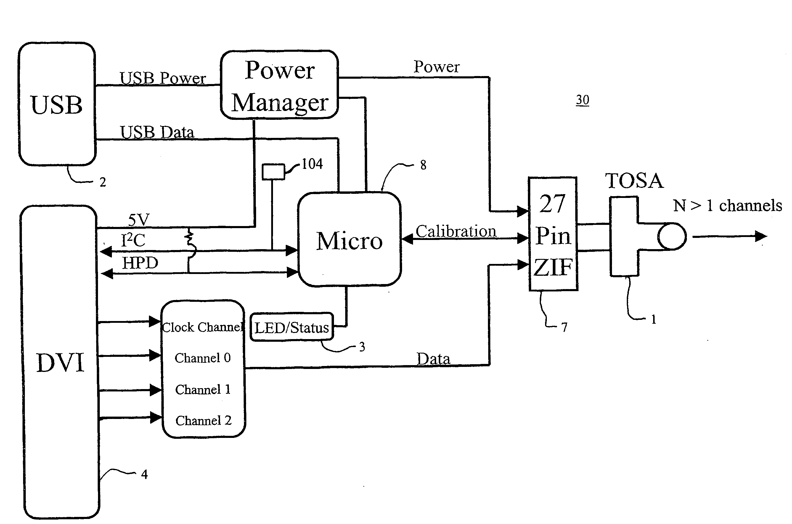
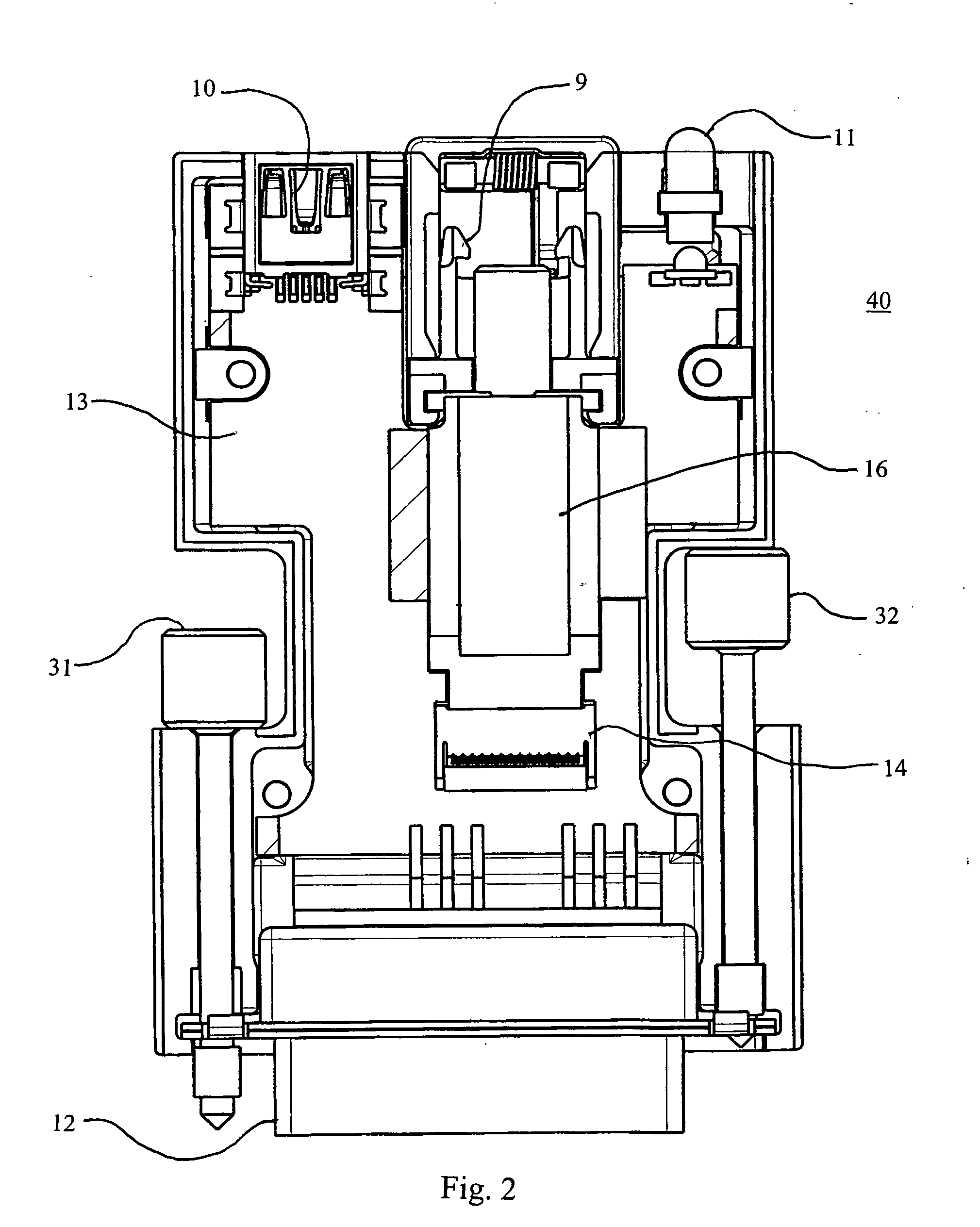
[0026]In order to solve the problems mentioned above and to achieve the purpose mentioned above, the DVI fiber optic extender devices of the present inventions include: a transmitter apparatus, or transmitting device, allowing transport of DVI dual link over one fiber optic cable, a receiver apparatus, or receiving device, allowing the receipt of DVI dual link over one fiber optic cable, a memory for storing information, a reading channel for reading information out of output destination devices, a Universal Serial Bus (USB) input device for power and memory management, and an Light Emitting Diode (LED) device which identifies the power on and signal on state of the device.

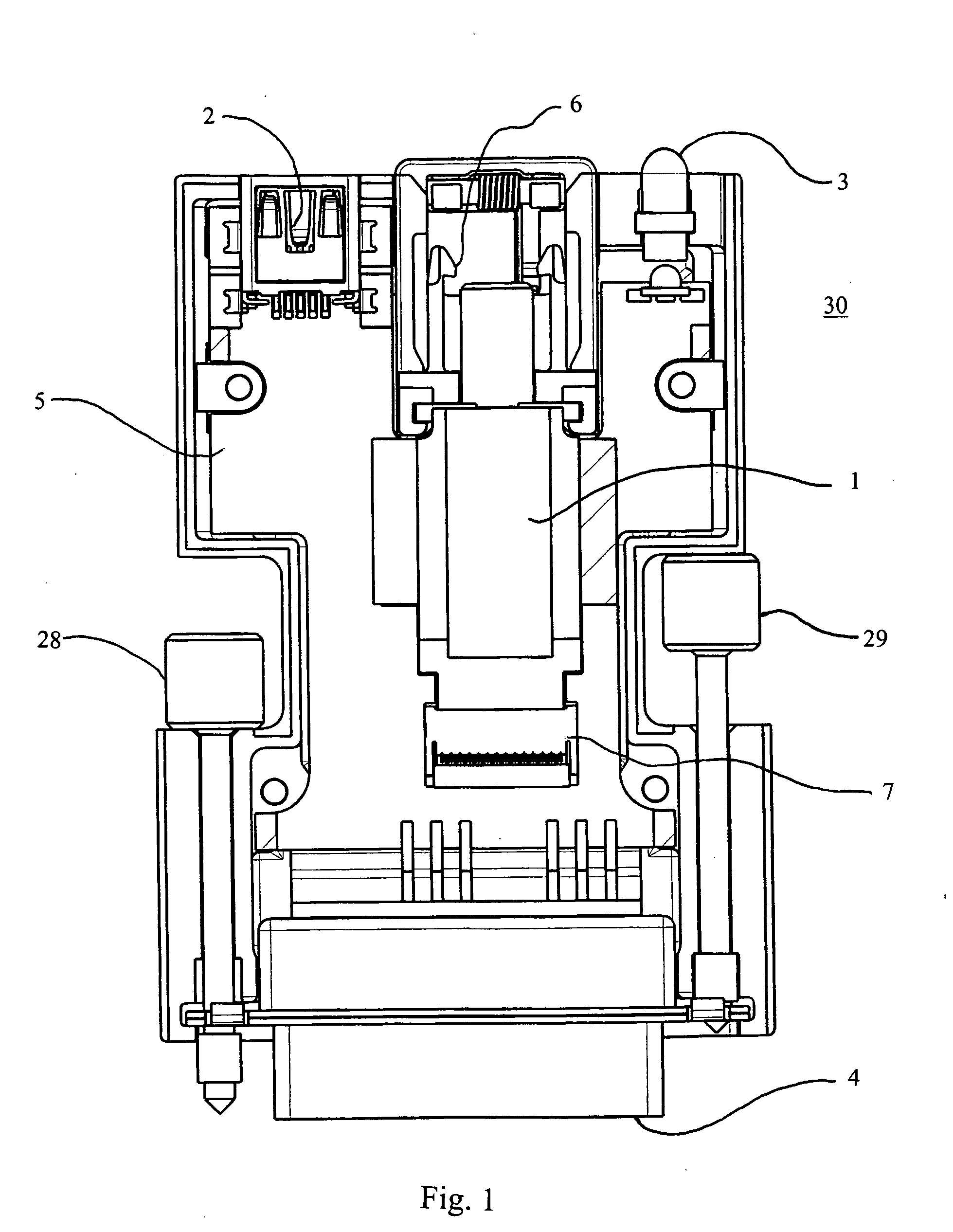
[0027]FIG. 1 discloses the major components of the transmitting device 30. Numeral designator 1 identifies a multichannel transmitter optical subassembly that is connected to the output processing circuit located on the printed circuit (PC) board 5 through a zero insertion force (ZIF) socket connector 7. The multi...


PUM


Abstract

A transmitting device includes a housing, a multichannel transmitter optical subassembly, a microcontroller, and a DVI connector. The housing has only one optical port, where the only one optical port is adapted to receive only one optical fiber. The multichannel transmitter optical subassembly is mechanically associated with the housing. The microcontroller is electrically associated with the multichannel transmitter optical subassembly. The DVI connector is mechanically associated with the housing. The transmitting device is adapted to convert at least four electrical TMDS signals into optical paths that are transmittable over the only one optical fiber. A receiving device is similar to the transmitting device, however, in contrast to the transmitting device, the receiving device includes a multichannel receiver optical subassembly, and wherein the receiving device is adapted to convert multiple colored wavelengths into at least four electrical TMDS signals.

Description

[0001]This non-provisional application claims the priority of earlier filed U.S. Provisional Application Ser. Nos. 60 / 967,909, filed Sep. 7, 2007, and 60 / 967,551, filed Sep. 5, 2007. U.S. Provisional Patent Application Ser. Nos. 60 / 967,909, and 60 / 967,551 are hereby incorporated herein by reference.BACKGROUND OF THE INVENTION[0002]1. Field of the Invention[0003]The present invention represents a method of intelligent signal distribution for matching transmitter and receiver devices provided by attaching both devices together by means of a single fiber optic cabling scheme.[0004]2. Discussion of the Background[0005]As digital distribution and media converter gear for transporting video images start to replace traditional analog Video Graphics Array (VGA), the amount of data required to maintain a quality image becomes more critical.[0006]One of the most popular digital interfaces is the Digital Video Interface (DVI). This interface includes high speed signal transmission lines withou...

Claims


Application Information

Patent Timeline
Patent Type & Authority Applications(United States)
IPC IPC(8): H04B10/06H04B10/12H04B10/00
CPCH04B10/40
Inventor CUNNEEN, JAMESHOLLAND, DANNY E.KOWALKOWSKI, ANTHONY S.TORRES, LUIS
Owner STRATOS INT
Learn More