Pecvd process chamber with cooled backing plate

Inactive Publication Date: 2009-03-19
APPLIED MATERIALS INC
View PDF4 Cites 40 Cited by
  • Summary
  • Abstract
  • Description
  • Claims
  • Application Information

AI Technical Summary

Problems solved by technology

If a diffuser is warped or sagged during the deposition process, the process may not produce the desired uniform deposition.
However, when relatively thick layers of semiconductor material are deposited in a PECVD chamber, such as is required to form the intrinsic layer of a photovoltaic cell,

Method used


Image

  • Pecvd process chamber with cooled backing plate
  • Pecvd process chamber with cooled backing plate
  • Pecvd process chamber with cooled backing plate

Examples


Embodiment Construction

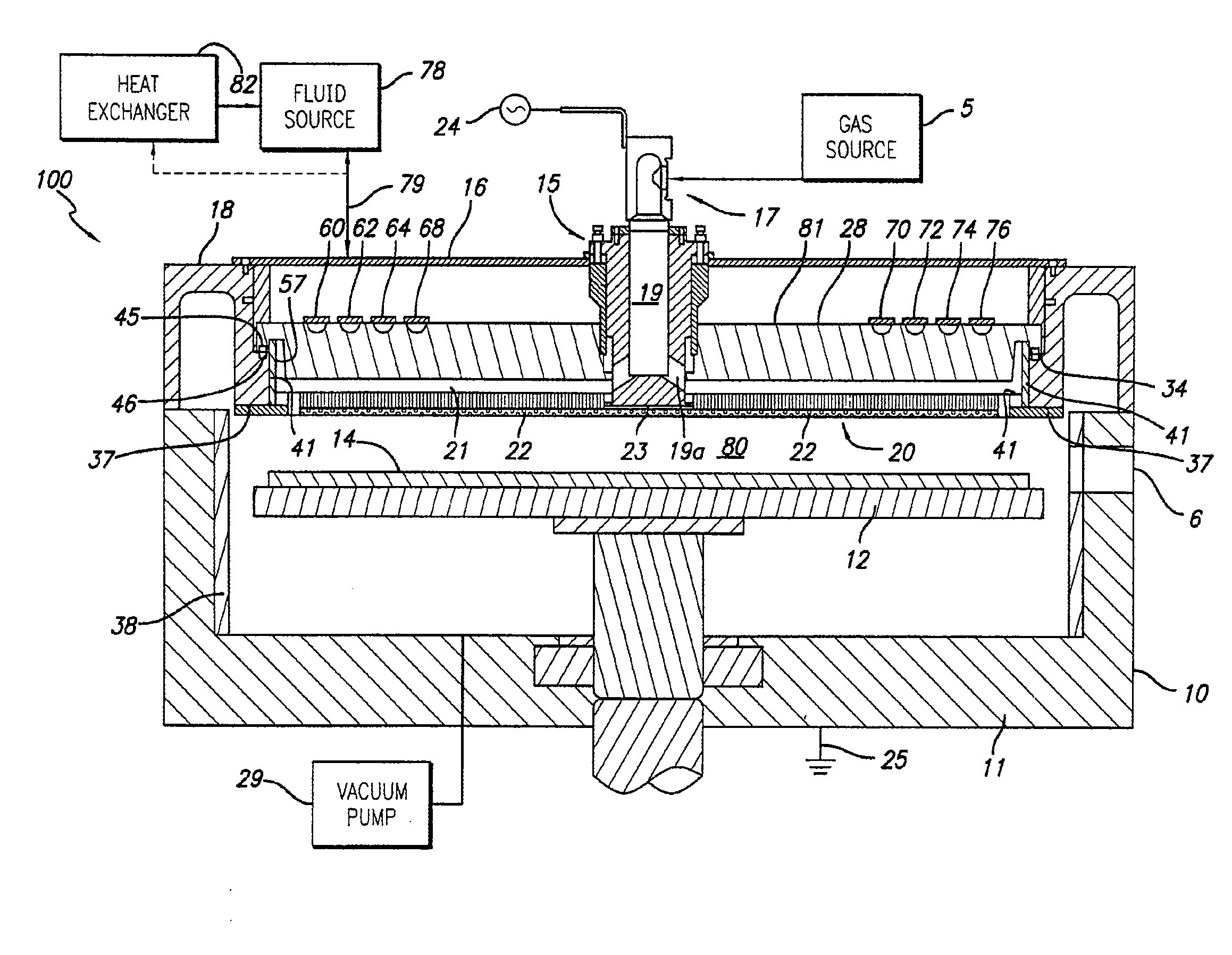
[0021]The embodiments of the present invention generally provide a plasma enhanced chemical vapor deposition chamber in which the backing plate is utilized to support the diffuser and in which the backing plate is constructed to have at least one fluid conduit in thermal transfer contact therewith. A fluid is circulated through the conduit and has a lower temperature upon being introduced into the conduit than when being removed from the conduits, thereby removing heat from the backing plate that was generated by the plasma during the deposition process. Through removal of heat from the backing plate, the backing plate is rendered more stable and in turn keeps the diffuser cooled and in proper alignment with respect to the substrate so that the material deposited on the substrate as a result of the plasma reaction is uniform.

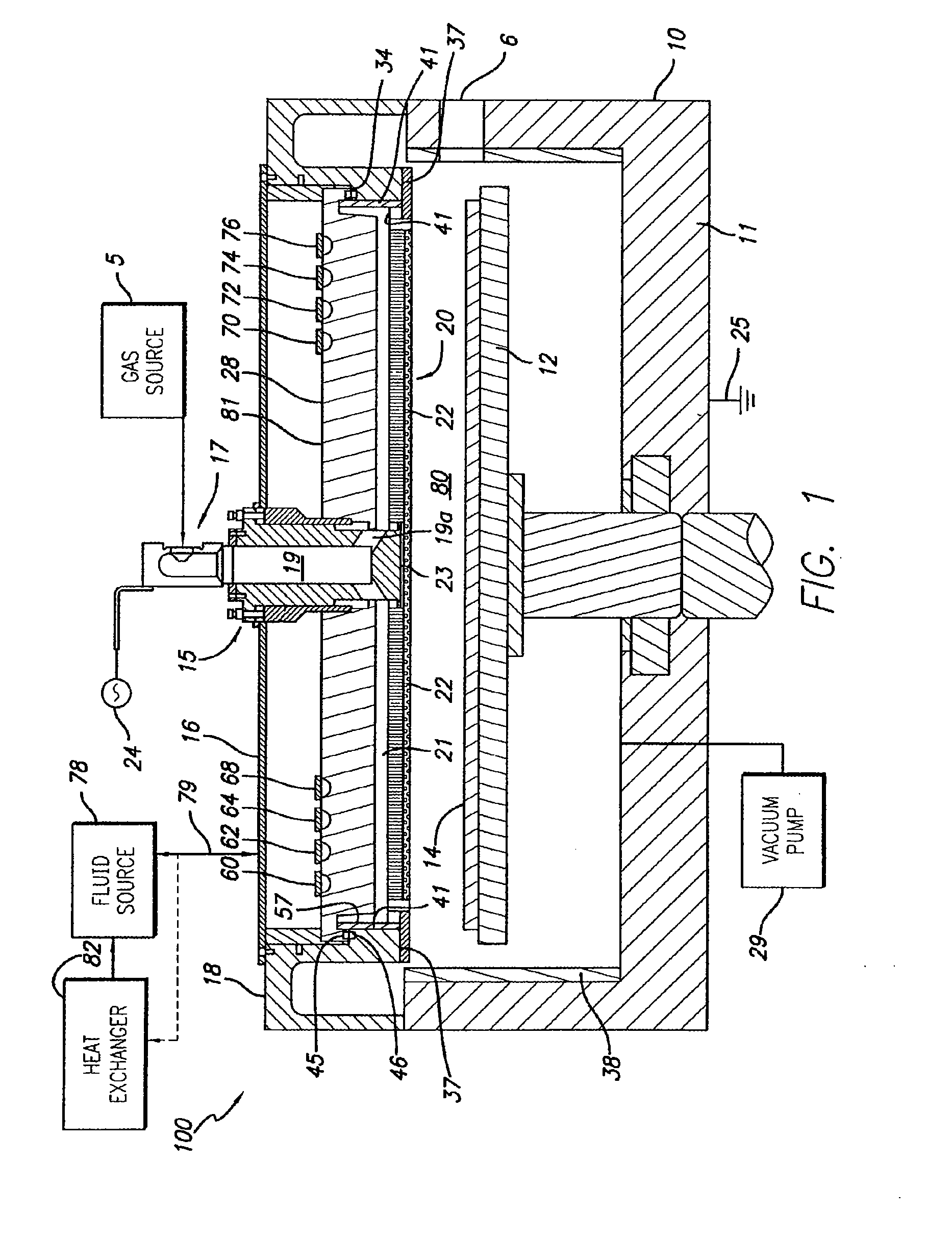
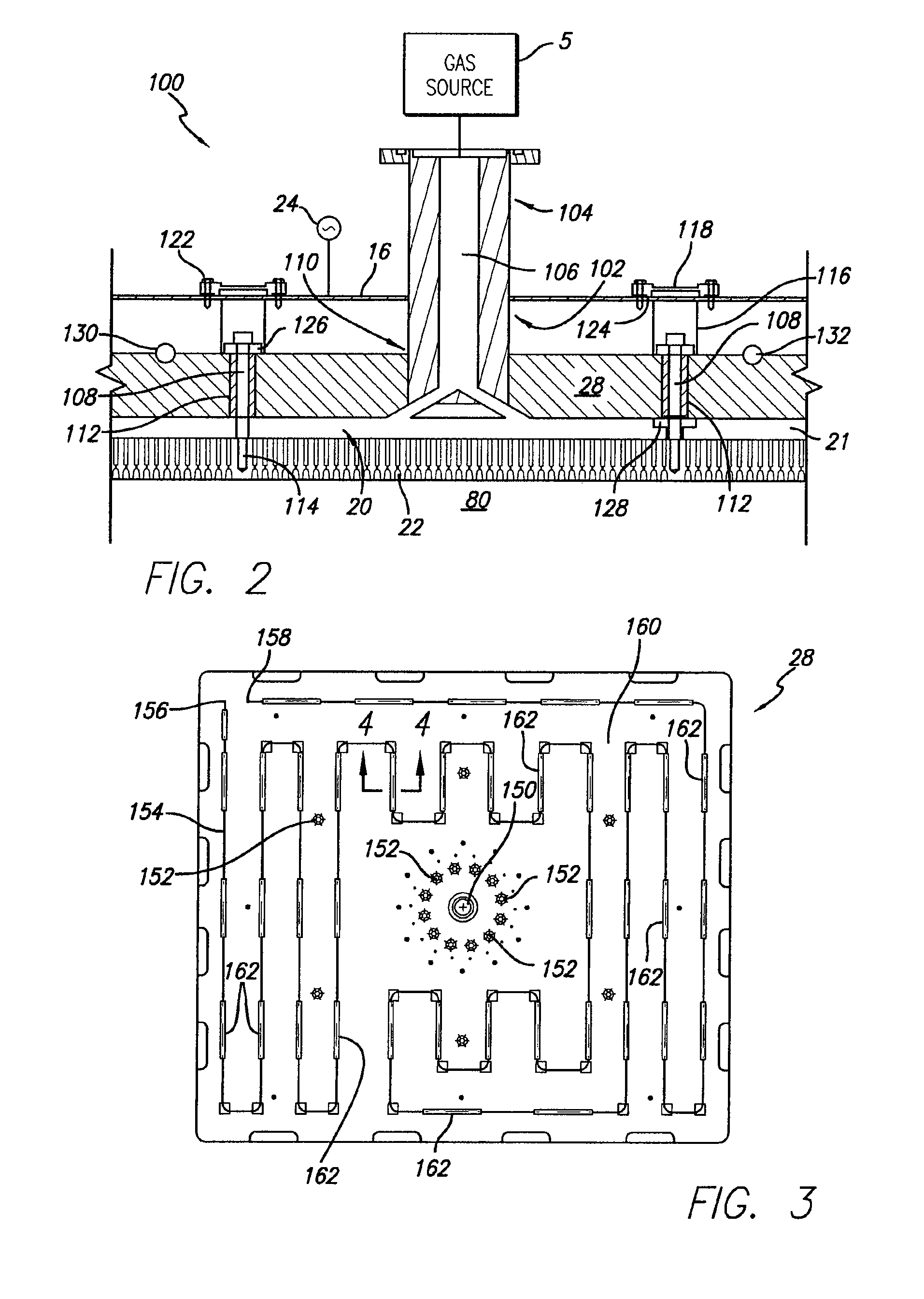
[0022]FIG. 1 is a side view in cross section of a chamber 100 that is suitable for plasma enhanced chemical vapor deposition (PECVD) processes for fabricating v...


PUM

PropertyMeasurementUnit
Timeaaaaaaaaaa
Temperatureaaaaaaaaaa
Areaaaaaaaaaaa

Abstract

The invention generally relates to a plasma enhanced chemical vapor deposition chamber for depositing amorphous or microcrystalline silicon on a glass substrate to fabricate solar voltaic cells. The chamber includes a backing plate having at least one fluid receiving conduit to receive cooling fluid to remove heat generated within the chamber by the plasma, thereby stabilizing and cooling the backing plate to assure the uniformity of deposition of materials on the surface of the substrate.

Description

CROSS-REFERENCE TO RELATED APPLICATIONS[0001]This application is a continuation-in-part of co-pending U.S. patent application Ser. No. 11 / 858,020 (APPM / 11712US), entitled “Cooled Backing Plate”, filed Sep. 19, 2007, which is incorporated herein by reference.BACKGROUND OF THE INVENTION[0002]1. Field of the Invention[0003]Embodiments of the present invention relates generally to a plasma enhanced chemical vapor deposition chamber and more specifically to controlling the temperature within the chamber during deposition of semiconductor materials on a suitable substrate to form photovoltaic cells.[0004]2. Description of the Related Art[0005]Plasma enhanced chemical vapor deposition (PECVD) chambers for the deposition of semiconductor materials on substrates is well known in the art. Examples of such PECVD chambers are shown in U.S. Pat. No. 6,477,980 and published Patent Application US 2006 / 0060138 A1, each of which is incorporated herein by reference. Plasma processes includes supplyin...

Claims


Application Information

Patent Timeline
IPC IPC(8): C23C16/513
CPCC23C16/24C23C16/45565H01J37/32522H01J37/3244C23C16/5096
Inventor CHOI, SOO YOUNGTINER, ROBIN L.WHITE, JOHN M.
Owner APPLIED MATERIALS INC
Why Eureka
Try Eureka