Heat exchanger

Inactive Publication Date: 2009-03-19
DAIKIN IND LTD
View PDF3 Cites 14 Cited by
  • Summary
  • Abstract
  • Description
  • Claims
  • Application Information

AI Technical Summary

Benefits of technology

[0017]The heat exchanger according to the third aspect of the present invention enables improvement of the heat transfer performance since a poor contact between the core pipe and the winding pipe will not be formed at least at the bending center portion of the bent part. In addition, when the core pipe and the winding pipe are

Problems solved by technology

However, when a heat exchanger is formed by spirally winding a winding pipe around the outer circumference of a jig, pulling out the jig so as to form a winding pipe body, and inserting a core pipe into the winding pipe body, there is a possibility that a poor contact may be formed between the core pipe and the winding pipe, consequently reducing the heat transfer performance.
In particular, when a core pipe having projections that are formed on the inner surface thereof by pressing the outer surface of the core pipe is used as a core pipe of a heat exchanger, since a cross-section at a bent part

Method used


Image

  • Heat exchanger
  • Heat exchanger
  • Heat exchanger

Examples


Embodiment Construction

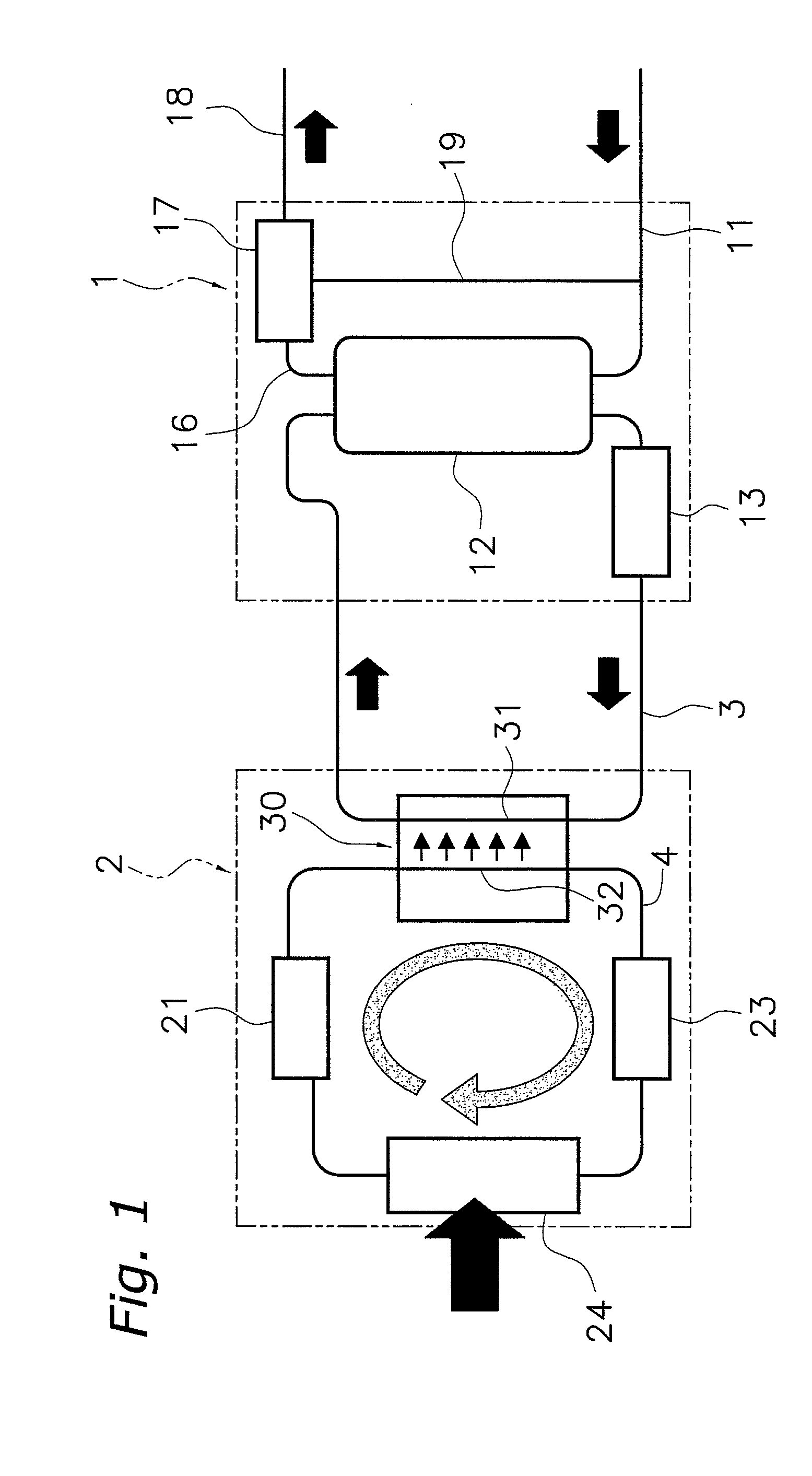
[0028]The heat exchanger according to the present invention will now be described based on the attached drawings and the embodiments. FIG. 1 is a schematic diagram of a heat pump water heater in which a heat exchanger of the present invention is employed. In the heat pump water heater shown in FIG. 1, water is heated in a single pass from about 10° C. to about 90° C. over a long time of period in order to efficiently use low-cost nighttime electric power. Here, the heat pump water heater includes a hot water supply unit 1, and a heat pump unit 2. The following are successively coupled in the hot water supply unit 1: a service water pipe 11, a hot water storage tank 12, a water circulation pump 13, a water supply pipe 3, a core pipe 31 that constitutes a water heat exchanger 30, a hot water pipe 16, a mixing valve 17, and a hot water supply pipe 18. Here, service water is supplied from the water supply pipe 11 to the hot water storage tank 12. Low temperature water is supplied by the...


PUM

PropertyMeasurementUnit
Circumferenceaaaaaaaaaa

Abstract

The outer surface of a core pipe 31 is pressed so as to form projections 313 on the inner surface of the core pipe 31, and a winding pipe 32 is helically wound around the outer circumference of the core pipe 31. Subsequently, the core pipe 31 and the winding pipe 32 are bent together, and brazing is performed. As a result, the outer surface of the winding pipe 32 is in contact with the outer surface of the core pipe 31 without any gap therebetween at a bending center portion (D), and the outer surface of the winding pipe (32) is bonded to the outer surface of the core pipe (31) by a brazing material (33) at the bending center portion (D) of the bent part C-C.

Description

FIELD OF THE INVENTION[0001]The present invention relates to a heat exchanger. More specifically, the present invention relates to a heat exchanger that includes a core pipe having projections that are formed on an inner surface thereof by pressing the outer surface of the core pipe, and a winding pipe that is wound around the outer surface of the core pipe.BACKGROUND OF THE INVENTION[0002]Some heat exchangers used for air conditioners, water heaters, and the like are provided with a core pipe that forms a passage of a first fluid, a winding pipe that is wound around the outer surface of the core pipe and forms a passage of a second fluid, and a heat exchanger that exchanges heat between the first fluid and the second fluid. For example, a double pipe heat exchanger is used as a heat exchanger for a water heater such as a heat pump water heater. Such a heat exchanger is formed by two pipes: a core pipe through which water flows and a winding pipe through which the refrigerant flows....

Claims


Application Information

Patent Timeline
IPC IPC(8): F28F1/10B21D53/06
CPCB21C37/158Y10T29/49362B21D53/06B23K1/0012B23K2201/06B23K2201/14F25B30/02F25B39/04F25B2339/047F28D7/0016F28D7/022F28F1/06F28F2210/06F28F1/426F28D7/024F28F2275/04B21C37/26B23K2101/06B23K2101/14B23K1/00F25B39/00F28D7/02
Inventor NUMATA, MITSUHARUSHIBATA, YUTAKA
Owner DAIKIN IND LTD
Why Eureka
Try Eureka