Device and associated method for measuring crosstalk

a crosstalk and device technology, applied in the field of crosstalk measurement, can solve problems such as negative impact on other communication lines, and achieve the effects of reducing the transmit power or psd of a communication line, and reducing the influence of that communication line on other communication lines

Inactive Publication Date: 2009-03-19
ALCATEL LUCENT SAS
View PDF9 Cites 17 Cited by
  • Summary
  • Abstract
  • Description
  • Claims
  • Application Information

AI Technical Summary

Benefits of technology

[0011]Lowering the transmit power or PSD of a communication line reduces the influence of that communication line on other communication lines. According to the present invention and in the case of the specific operation parameter being the SNR, these changes are measured in a standard compliant and backwards compatible fashion through SNR measurements and the measured SNR changes can be related to the amplitude and phase of the crosstalk between various communication channels. In addition, by lowering the transmit power or PSD there is at least temporarily a reduced influence from that line on the other communication lines. Thus, the estimation of the amplitude and phase of the crosstalk itself has hardly any or no negative impact on the operation of the other communication lines. The lowering of the transmit power of strong crosstalkers has the advantage that the crosstalk from weak crosstalkers can be observed with a larger accuracy. Alternatively, raising the transmit power or PSD also enables determining the amplitude and phase of crosstalk between various communication lines but may have a negative impact on the other communication lines, for instance due to a stronger crosstalk influence. It is of course also possible to perform a first SNR measurement after decreasing and a second SNR measurement after increasing the transmit power, or changing the transmit power or PSD can be performed after other changes to the condition of one or more communication lines have been executed in order to avoid significant influences on the communication lines during the measurement.
[0016]By implementing one or more On-Line Reconfiguration (OLR) commands, changing the transmit power and / or PSD during show-time becomes more flexible. Such OLR commands provide a way to both ends of a communication line to change the current conditions of the communication line, for instance those as agreed during initialization. These OLR commands can for instance be used to change the transmit power, PSD, TSSi coefficients, data rate, etc.
[0022]The addition of artificial noise on one or more tones of one or more communication lines decreases the noise margin on these communication lines. As a consequence of the change in noise margin, the data rate on the communication lines may be decreased by autonomous action of the receiver (e.g. based on Seamless Rate Adaptation (SRA) as defined in ITU-T G.992.3, G.992.5, G.993.2). By reducing the artificial noise after the data rate is lowered, an additional noise margin is created, which can be used for coping with the extra crosstalk, generated in the case of the method using an increase of the PSD on the disturber lines, to allow the measurement of operational parameters and the reporting thereof. After the measurement, the increased PSD is removed, and the data rate is allowed to increase back to its original value, for instance by autonomous action of the receiver. However, it may increase to a data rate higher than the original data rate or remain below the original data rate.
[0025]reducing the data rate on one or more of the plurality of communication lines using an On-Line Reconfiguration OLR command prior to the step of receiving the measured operational parameters; and

Problems solved by technology

Alternatively, raising the transmit power or PSD also enables determining the amplitude and phase of crosstalk between various communication lines but may have a negative impact on the other communication lines, for instance due to a stronger crosstalk influence.

Method used


Image

  • Device and associated method for measuring crosstalk
  • Device and associated method for measuring crosstalk
  • Device and associated method for measuring crosstalk

Examples


Embodiment Construction

)

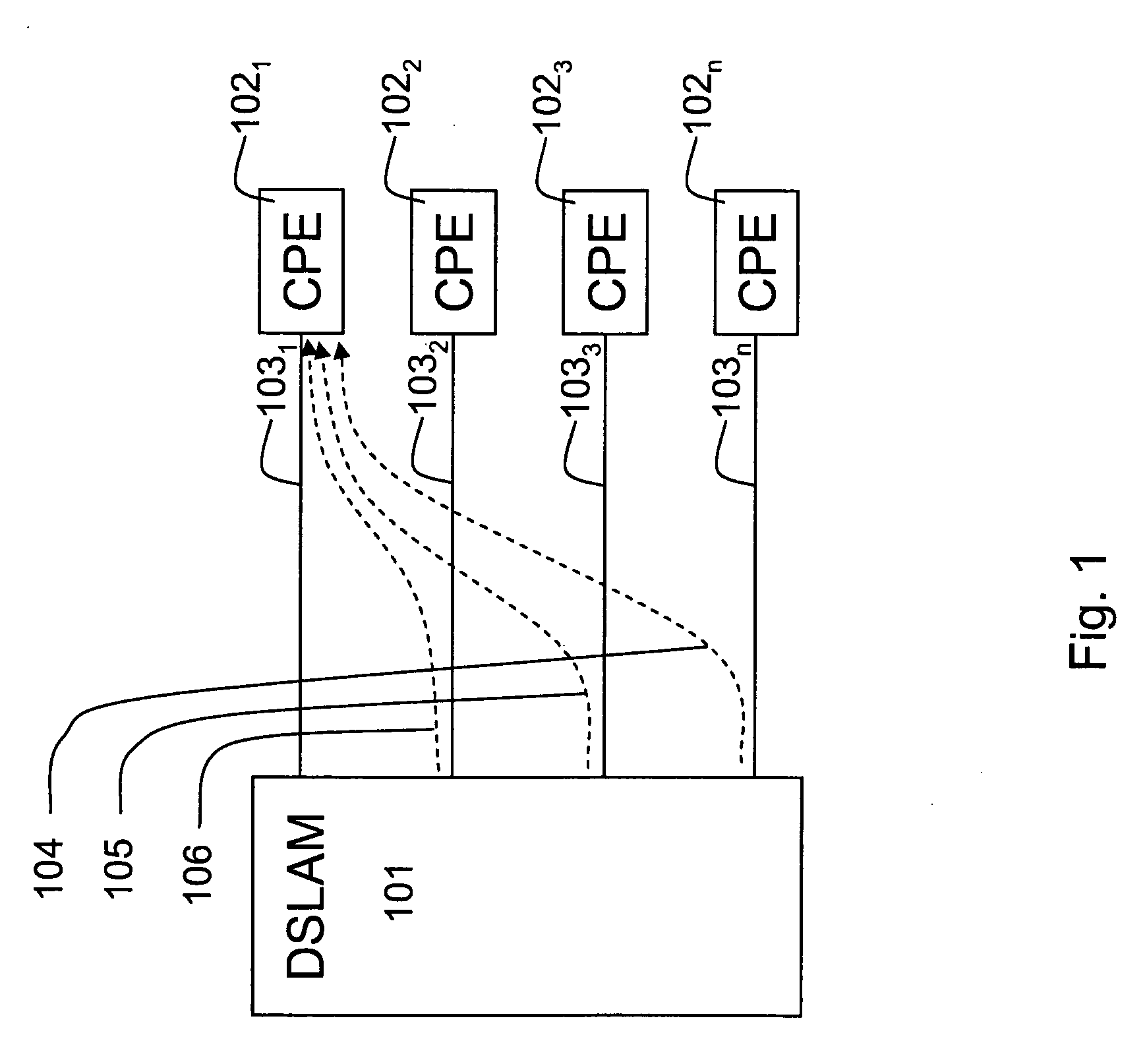
[0031]FIG. 1 illustrates a typical scenario wherein an embodiment of the crosstalk estimation device according to the present invention is used. FIG. 1 shows a number of communication lines, terminated at one side in a Central Office (CO) and at various locations such as houses or office buildings, on the other side. In particular, FIG. 1 shows a Digital Subscriber Line Access Multiplexer (DSLAM) 101 at the CO, a set of Customer Premises Equipment (CPE) 1021 to 1024 and a number of Digital Subscriber Lines (DSL) 1031 to 1034 connecting the DSLAM 101 respectively to the CPEs 1021 to 1024. In this particular example, we will assume that DSL line 1031 is the victim line and DSL lines 1032 to 1034 are the disturber lines.

[0032]The DSLAM 101 will configure the transmit power 104, 105 and 106 for transmission on the DSL lines 1032 to 1034 individually. The CPE 1021 is supposed to be able to measure the Signal to Noise Ratio SNR. Once the CPE 1021 has information related to the SNR or the...


PUM


Abstract

The present invention relates to a crosstalk estimation device for estimating crosstalk between disturber communication lines and victim communication lines. The crosstalk estimation device is able to change the power spectral density PSD on the victim communication lines and / or the disturber communication lines. The crosstalk estimation device further receives measured changes in operational parameters on the victim communication lines and / or disturber communication lines in order to estimate the crosstalk induced in the victim communication lines and / or disturber communication lines.

Description

FIELD OF THE INVENTION [0001]The present invention generally relates to crosstalk measurement and more in particular to crosstalk measurement between multiple communication lines.BACKGROUND OF THE INVENTION [0002]Transmission of data at high speeds, for instance in Asymmetric Digital Subscriber Line (ADSL) or Very high-speed Digital Subscriber Line (VDSL) networks, commonly referred to as xDSL networks is subject to noise injected by external sources. One particular problem is the influence of crosstalk between various subscriber lines within close vicinity. Crosstalk is the effect whereby a first subscriber line induces signals on a second, different subscriber line, which act as noise on that second subscriber line. Such effects are especially noticed when multiple subscriber lines form part of the same cable or cable binder or when they are terminated close to each other, for instance in a Digital Subscriber Line Access Multiplexer (DSLAM) where multiple subscriber lines are term...

Claims


Application Information

Patent Timeline
Patent Type & Authority Applications(United States)
IPC IPC(8): H04J1/12
CPCH04L27/2601H04B3/487H04M3/34H04M3/303
Inventor GUENACH, MAMOUNVAN BRUYSSEL, DANNYYSEBAERT, GEERT BERT MAARTENMAES, JOCHENPEETERS, MICHAEL
Owner ALCATEL LUCENT SAS
Why Eureka
Try Eureka