Turbine and compressor employing tubercle leading edge rotor design

a technology of leading edge rotor and turbine, which is applied in the direction of wind motor with parallel air flow, liquid fuel engine components, wind energy generation, etc., can solve the problems of increasing scale, scarceness, and “prime sites” of wind and water turbines, so as to improve the lift-to-drag ratio, reduce drag, and improve the effect of lifting-to-drag ratio

Active Publication Date: 2009-03-19
WHALE POWER CORP
View PDF11 Cites 38 Cited by
  • Summary
  • Abstract
  • Description
  • Claims
  • Application Information

AI Technical Summary

Benefits of technology

The turbine/compressor described in this patent has several advantages. First, the design reduces drag by using rotor blades that generate additional lift, which improves the ratio of lift to drag. This means that less structural strength is needed for the supporting towers, resulting in lower costs. Additionally, by adjusting the orientation of the rotor blades so they are more steeply pitched into the fluid flow, lift can be further enhanced. This improved design also reduces drag, allowing the rotor blade to operate over a wider range of fluid flow rates and increasing the amount of power that can be captured from the available fluid flow. The shape of the rotor blades also helps to reduce noise and pumping.

Problems solved by technology

The technical problem addressed in this patent text is the need for improvements in wind and water turbine design that offer increased efficiency without significant increases in costs. The current technologies for low wind speed turbines have been largely incremental rather than fundamental, with researchers exploring options such as larger turbines, taller towers, more efficient generators, flexible turbines, and improved control and monitoring technology. The challenge is to design turbines that offer more efficient power generation without exceeding practical limits on size and cost.

Method used


Image

  • Turbine and compressor employing tubercle leading edge rotor design
  • Turbine and compressor employing tubercle leading edge rotor design
  • Turbine and compressor employing tubercle leading edge rotor design

Examples


Embodiment Construction

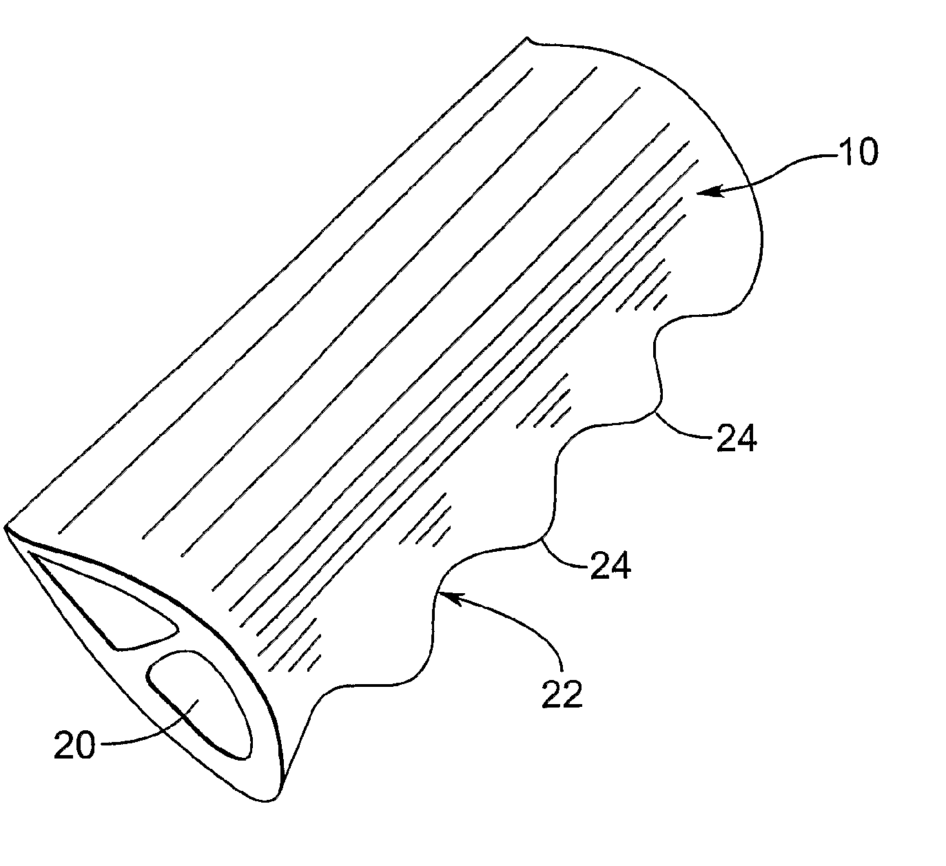
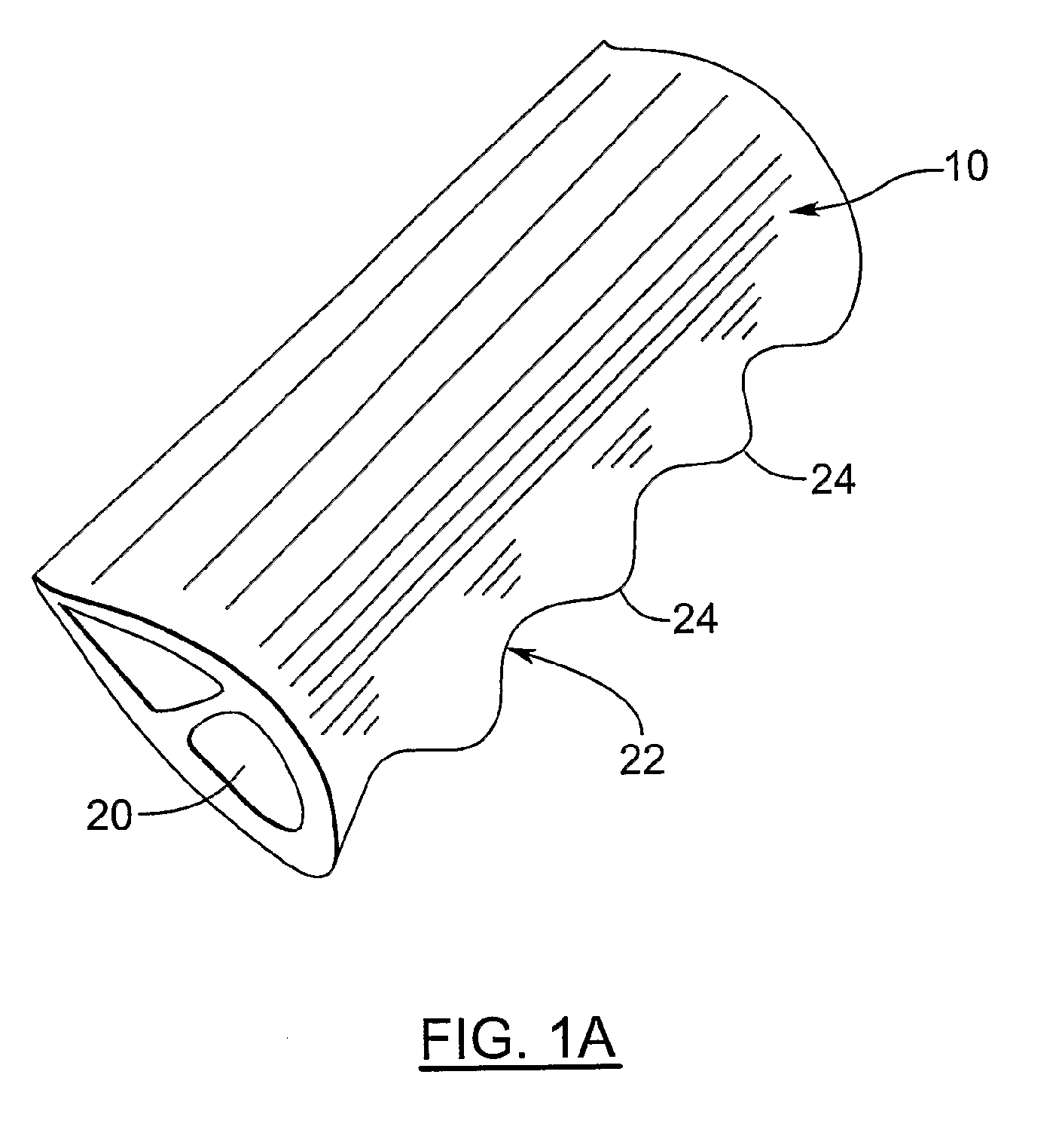
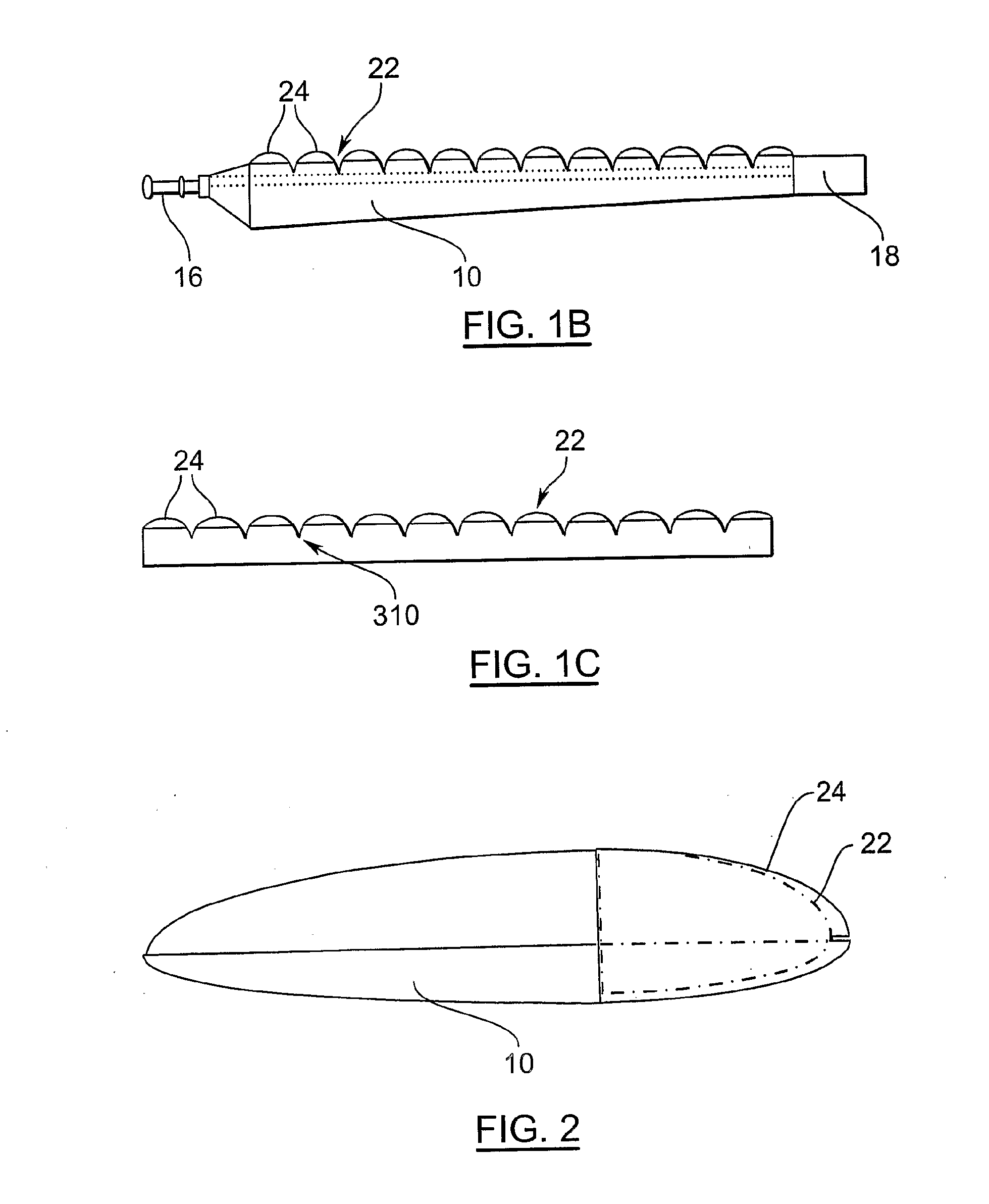
[0031]Turning now to FIGS. 1A, 1B and 2, a turbine rotor blade is shown and is generally identified by reference numeral 10. As can be seen, the turbine rotor blade 10 is coupled to a fixed hub 12 (see FIG. 3A) and has a blade body 14 extending from a root 16 to a blade tip 18. A structural beam such as a D-spar 20 is integrally formed within the blade body 14 allowing rotational power to be transmitted to the hub 12. The blade body 14 has a leading edge 22.

[0032]Unlike conventional turbine rotor blades, the leading edge 22 is provided with tubercles 24 along its length between the root 16 and the blade tip 18 similar to those described in U.S. Pat. No. 6,431,498, the content of which is incorporated herein by reference. The tubercles 24 in this case are generally evenly spaced along the leading edge 22 and provide the rotor blade 10 with enhanced lift and better stall characteristics while at the same time, reducing the drag that the rotor blade 10 exhibits.

[0033]Although not illus...


PUM


Abstract

A turbine/compressor comprises at least one magneto electric device and a drive train coupled to the magneto electric device. At least one rotor blade is coupled to the drive train. The rotor blade has a shaped leading edge with a series of spaced tubercles formed therealong.

Description


Claims


Application Information

Patent Timeline
Owner WHALE POWER CORP
Why Eureka
Try Eureka