Method for blood vessel clip application

a blood vessel and clip technology, applied in the field of minimally invasive vascular surgery, can solve the problems of requiring patients to suffer, permanent deformation, and bulky surgical instruments in the pas

Inactive Publication Date: 2009-03-19
GEN SURGICAL INNOVATIONS
View PDF33 Cites 77 Cited by
  • Summary
  • Abstract
  • Description
  • Claims
  • Application Information

AI Technical Summary

Benefits of technology

[0007]In another aspect of a preferred embodiment, a return spring within the grip assembly is attached at one end to the ratchet rod to retract the ratchet rod at the end of its stroke, and at its other end to a revolving member which prevents the return spring from twisting or kinking during rotation of the applicator barrel.
[0008]In an alternate embodiment, a plunger applies a blood vessel clip with a direct stroke. In an aspect of the alternate embodiment, a spring or springs bias the plunger downward to contact a plurality of blood

Problems solved by technology

Such surgical instruments have in the past been bulky enough to require a cannula having an internal diameter of 10 mm or even 12 mm in order to insert them through the cannula to reach the operative site.
But, as stated above, known surgical instruments for applying blood vessel clips are too large to fit into a cannula having a 5 mm internal diameter, thus requiring the patient to suffer through insertion of a larger-than-optimal cannula for occlusion of blood vessels ha

Method used


Image

  • Method for blood vessel clip application
  • Method for blood vessel clip application
  • Method for blood vessel clip application

Examples


Embodiment Construction

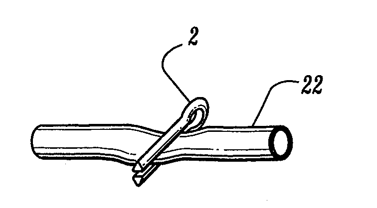
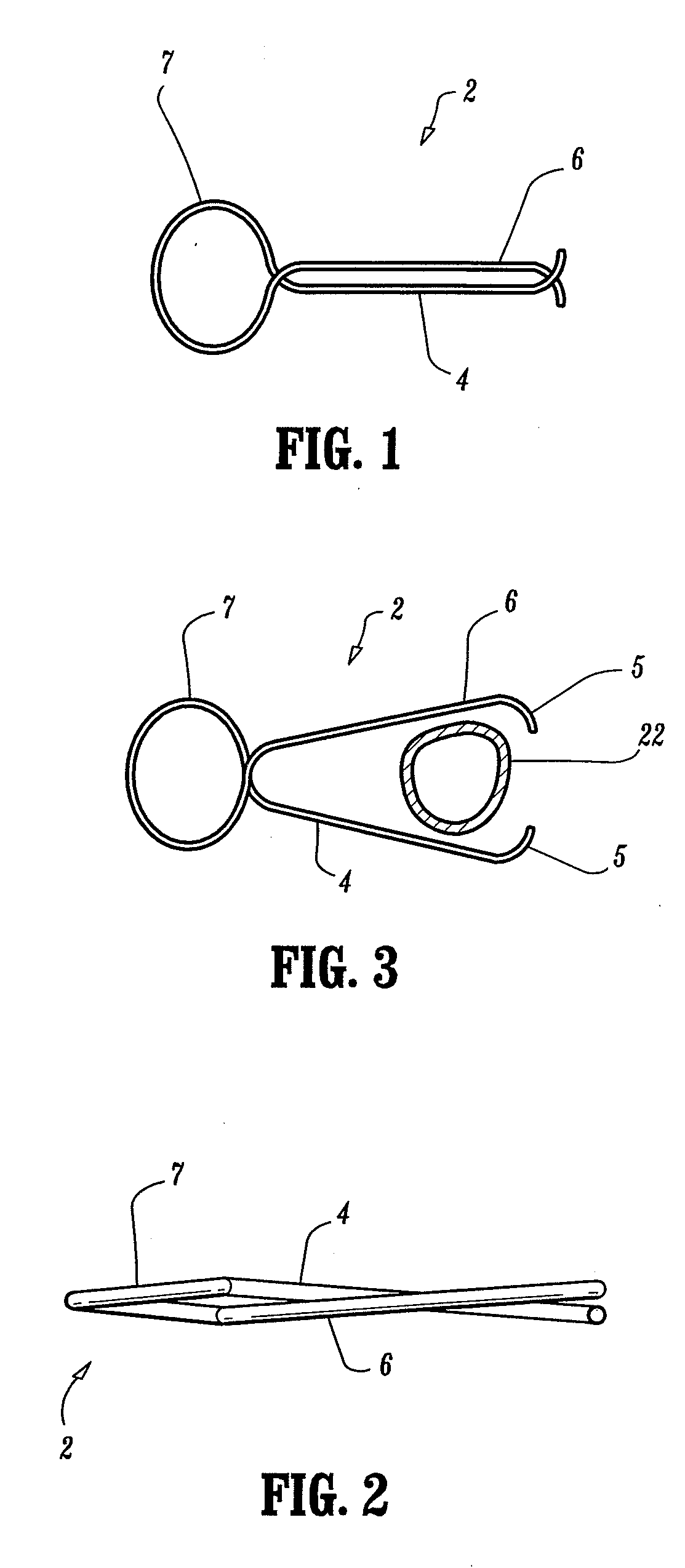
[0039]Referring to FIG. 1, a preferred embodiment of a blood vessel clip 2 can be seen. A first leg 4 and a second leg 6 are connected by a head 7. In a preferred embodiment, the head 7 is substantially circular. A top view of the preferred blood vessel clip 2 can be seen in FIG. 1, and a side view of the blood vessel clip 2 can be seen in FIG. 2. As can be seen, the first leg 4 crosses over the second leg 6. However, it is equally effective to manufacture the blood vessel clip 2 such that the first leg 4 crosses under the second leg 6. In a preferred embodiment, the proximal end of the first leg 4 is located substantially above the proximal end of the second leg 6, and the distal end of the first leg 4 is located substantially below the distal end of the second leg 6. By arranging the first leg 4 and the second leg 6 in this manner, the lateral stability of the blood vessel clip 2 is increased.

[0040]In a preferred embodiment, the blood vessel clip 2 comprises a spring-quality mater...


PUM

PropertyMeasurementUnit
Forceaaaaaaaaaa
Shapeaaaaaaaaaa

Abstract

A blood vessel clip applicator preferably includes two twist pins at one end, between which a blood vessel is placed before occlusion. A magazine in the blood vessel clip applicator preferably holds a plurality of blood vessel clips and can be rotated independently from a grip assembly, whereby the twist pins can be rotated to compress a blood vessel held between them. A blood vessel clip is preferably placed on the blood vessel after it has been flattened.
A blood vessel clip preferably comprises spring quality material, and preferably has a head connected to a first leg and a second leg. The magazine preferably has a constricted region adjacent to an exit aperture. As the head enters the constricted region, the compressive force exerted on the head by the constricted region opens the blood vessel clip to an open position.
In an alternate embodiment, a plunger applies a blood vessel clip with a direct stroke. The plunger has a plurality of stepwise indentations used to restrain the blood vessel clips before application and for pushing them all forward substantially simultaneously during application.
In an alternate embodiment, a variety of blood vessel clips having different shapes, cross-sections and grooves are suitable for use with the blood vessel clip applicator. The alternate blood vessel clip preferably have two legs in a “V” configuration and a head connecting the two legs. The constricted region compresses the head of the blood vessel clip as it passes through the constricted region, thereby closing the clip onto the blood vessel. These alternate embodiments may comprise substantially annealed metal.

Description

[0001]The field of invention is minimally invasive vascular surgery, and more specifically an apparatus and method for occluding a blood vessel with clips applied with an applicator extending through a cannula.[0002]Minimally invasive surgery has grown in popularity in the past decade. Minimally invasive surgery (MIS) allows a surgeon to treat a patient while making only tiny incisions in the patient's body, through which surgical devices called cannulae are inserted. A cannula is essentially a thin, hollow tube through which other surgical tools can be inserted into and withdrawn from the patient's body. Because only a small incision is made in the patient's skin for insertion of a cannula, the patient heals faster and experiences less pain than in the aftermath of conventional surgery, in which larger incisions and tools are used.[0003]In several minimally invasive procedures, blood vessels in a patient are permanently occluded. Two common procedures involving blood vessel occlusi...

Claims


Application Information

Patent Timeline
IPC IPC(8): A61B17/122A61B17/12A61B17/00A61B17/128
CPCA61B17/122A61B17/1227A61B2017/00429A61B2017/0042A61B17/1285
Inventor KAYAN, HELMUTJERVIS, JAMES E.
Owner GEN SURGICAL INNOVATIONS
Why Eureka
Try Eureka