
Method of monitoring positioning of polymer stents

a technology of stent positioning and monitoring method, which is applied in the field of monitoring positioning of polymer stents, can solve the problems of increasing thrombosis, and achieve the effects of increasing or decreasing the diameter of the stent, increasing blood flow turbidity, and increasing thrombosis

Inactive Publication Date: 2009-03-19
ARTERIAL REMODELING TECH SA
View PDF12 Cites 79 Cited by
  • Summary
  • Abstract
  • Description
  • Claims
  • Application Information

AI Technical Summary

Benefits of technology

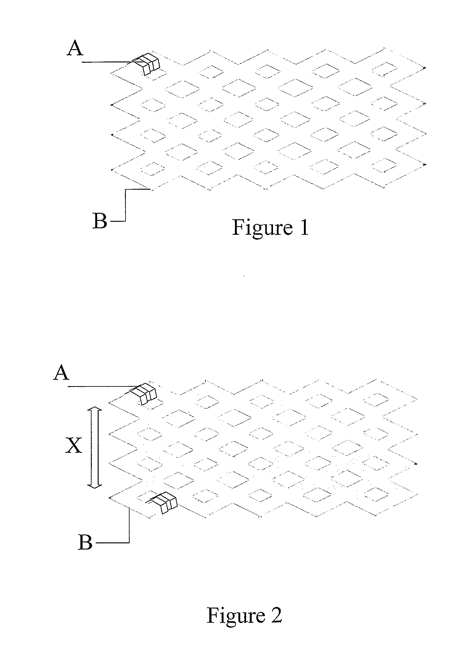
[0009]The markers may be used to track the location of the stent as it travels through the body. This greatly assists the physicians in determining if the stent is traveling the correct path through the vasculature. This further assists the physician in placing the stent at the correct site within the lumen. In some embodiments, these markers can also be used to monitor the stent position after placement and to monitor absorption of bioabsorbable stents.
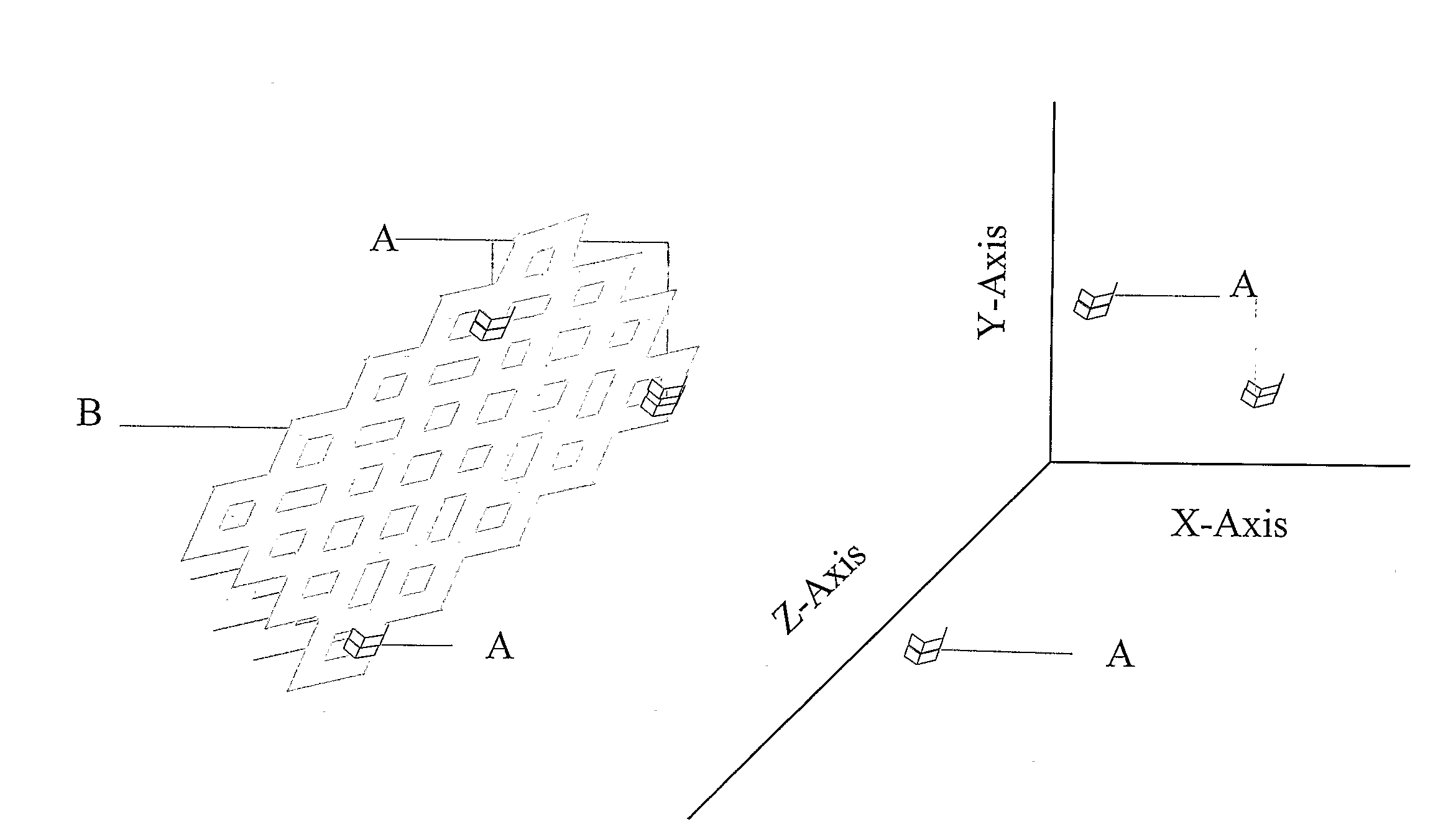
[0010]In certain embodiments, it is contemplated that the stent may comprise at least two markers placed such that the diameter of the stent may be determined in real time. This feature helps to determine if a crimped stent has been properly expanded. The placement of such markers may also determine at any time if the diameter of the stent has increased or decreased.
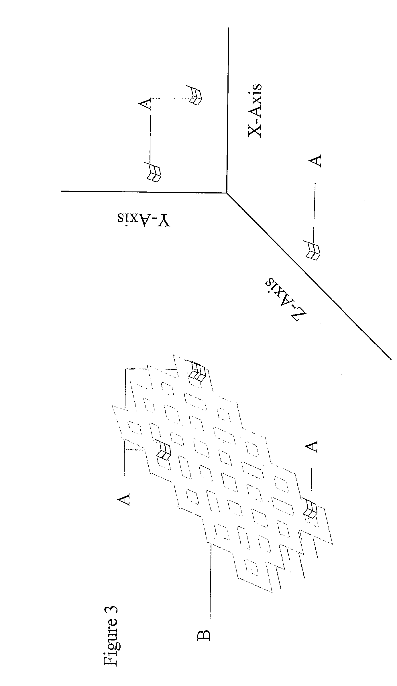
[0011]In certain embodiments, it is also contemplated that the stent may comprise at least three markers. The use of at least three markers enables the three dimensional location of the stent to be determined at any time. This feature can be used to determine if the stent has a rotational motion within the lumen. Rotational motion of the stent within the lumen is disfavored because it increases blood flow turbidity, which increases thrombus formation.
[0012]In certain embodiments, it is also contemplated that the stent may comprise markers such that the markers are located in regions with different in vivo lifetimes. Stent regions with different in vivo lifetimes means that the in vivo lifetime of the region is predetermined and found to be different from the in vivo lifetime of a different region. This feature enables one to determine the degradation pattern of the stent in real time.
[0013]In certain embodiments, it is contemplated that the pattern and material type of markers on the stent may be such that one can determine the type of stent inserted within a lumen or within a box. This feature may greatly assist in determining and monitoring what type of stents is located within a package as the packages travel through the supply chain. This feature may also assist in determining what type of stent is located within a person post-implantation.

Problems solved by technology

Rotational motion of the stent within the lumen is disfavored because it increases blood flow turbidity, which increases thrombus formation.

Method used


Image

  • Method of monitoring positioning of polymer stents
  • Method of monitoring positioning of polymer stents
  • Method of monitoring positioning of polymer stents

Examples


Embodiment Construction

[0019]It will be appreciated by those skilled in the art that although the following Detailed Description will proceed with reference being made to preferred embodiments, the present invention is not intended to be limited to these embodiments.

[0020]In one embodiment, the present invention is directed to a polymer stent that comprises at least one marker, where the marker is provided to track the stent during its placement within the body. The stent of the present invention can have virtually any configuration that is compatible with the body lumen in which it is implanted for the purpose of repairing the same. Typically, stents are composed of an intricate geometric pattern of circumferential and longitudinally extending members. These elements are commonly referred to as struts.

I. Detectable Marker

[0021]The markers can be made of any material that may be detected external to the body. The only limitation on the type of marker used is that it be visible by external means and may be...


PUM

PropertyMeasurementUnit
thicknessaaaaaaaaaa
thicknessaaaaaaaaaa
thicknessaaaaaaaaaa

Abstract

The invention is directed to a polymer stent with one or more markers such that when the stent is placed within a lumen, the markers can be detected external to the body. The markers can also be used to monitor the stent position after placement and absorption of bioabsorbable stents. Further, the stent may comprise two markers used to determine the diameter of the stent in real time. It is also contemplated that the stent may comprise at least three markers. The use of at least three markers enables the three dimensional orientation of the stent to be determined at any time. The stent may also comprise markers such that the markers are located in regions with different in vivo lifetimes. It is also contemplated that the pattern and material type of markers on the stent may be used to determine the type of stent within a lumen or box.

Description

BACKGROUND OF THE INVENTION[0001]The use of stents in various surgical, interventional cardiology, and radiology procedures has quickly become accepted as experience with stent devices accumulates and as the advantages of stents become more widely recognized. Stents are often used in body lumens to maintain open passageways such as in the prostatic urethra, the esophagus, the biliary tract, intestines, and various coronary arteries and veins, as well as more remote cardiovascular vessels such as the femoral artery.[0002]Stents are often used to treat atherosclerosis, a disease in which vascular lesions or plaques consisting of cholesterol crystals, necrotic cells, lipid pools, excess fiber elements and calcium deposits accumulate in the walls of an artery. One of the most successful procedures for treating atherosclerosis is insertion of a deflated balloon within the lumen, adjacent the site of the plaque or atherosclerotic lesion. The balloon is then inflated to put pressure on and...

Claims


Application Information

Patent Timeline
Patent Type & Authority Applications(United States)
IPC IPC(8): A61F2/06A61B19/00A61F2/82
CPCA61B19/54A61F2/82A61F2/91A61F2/915A61F2002/91541A61L31/18A61F2210/0004A61F2250/003A61F2250/0098A61L31/148A61F2002/91558A61B90/39
Inventor SABARIA, PATRICK
Owner ARTERIAL REMODELING TECH SA
Learn More