Medical device suitable for use in treatment of a valve

a technology for valve leaflets and medical devices, applied in the field of surgical devices and methods, can solve the problems of valve leaflet failure, increased blood pressure in the lungs or liver, and reduced forward blood flow

Inactive Publication Date: 2009-03-19
MEDNUA
View PDF25 Cites 144 Cited by
  • Summary
  • Abstract
  • Description
  • Claims
  • Application Information

AI Technical Summary

Benefits of technology

[0003]Dysfunction of the cardiac AV valves is common and can have profound clinical consequences. Failure of the AV valves to prevent regurgitation leads to an increase in the pressure of blood in the lungs or liver and reduces forward blood flow. Valvular dysfunction either results from a defect in the valve leaflet or supporting structure, or dilation of the fibrous ring supporting the valve. These factors lead to a failure of valve leaflets to meet one another, known as co-aptation, allowing the blood to travel in the wrong direction.
[0144]The stability of the treatment element may be maintained either by a wire support anchored in the ventricular wall, or by supports anchored in the walls of the atrium. The shape of the treatment element may be designed to use the regurgitant jet to force it into the correct position.

Problems solved by technology

Failure of the AV valves to prevent regurgitation leads to an increase in the pressure of blood in the lungs or liver and reduces forward blood flow.
These factors lead to a failure of valve leaflets to meet one another, known as co-aptation, allowing the blood to travel in the wrong direction.
These treatments are considerable surgical operations requiring cardiopulmonary bypass and are associated with significant morbidity.
In many instances patients are too sick or too frail to undergo these operations and hospital stays and recovery phases after such operations are prolonged.
Percutaneous procedures are performed under local anaesthetic and the incisions required to perform the procedures are extremely small.

Method used


Image

  • Medical device suitable for use in treatment of a valve
  • Medical device suitable for use in treatment of a valve
  • Medical device suitable for use in treatment of a valve

Examples


Embodiment Construction

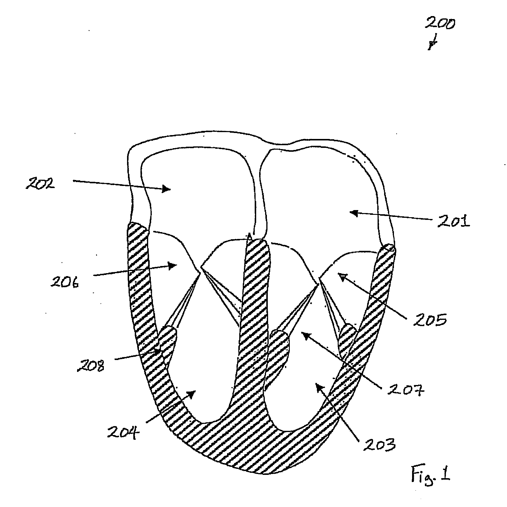
[0190]FIG. 1 illustrates the anatomy of a heart 200. The heart 200 has a left atrium 201, a right atrium 202, a left ventricle 203 and a right ventricle 204. Also illustrated are the mitral valve 205, the tricuspid valve206, the chordae tendiniae 207 and the papillary muscle 208.

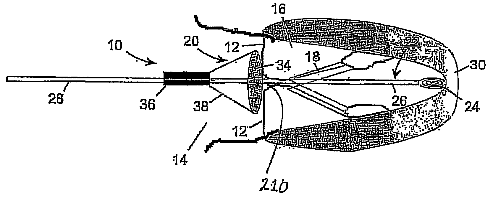
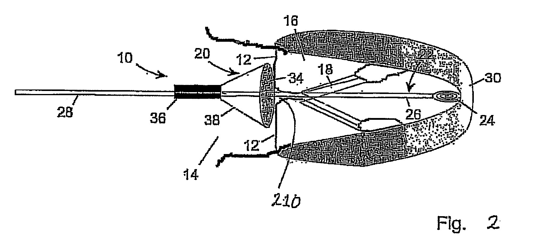
[0191]Referring to FIGS. 2 to 9 there is illustrated a medical device 10 according to the invention. The device 10 is suitable for use in treatment of a valve. The device 10 is particularly suitable for treating the mitral valve 205 to prevent retrograde blood flow through the mitral valve 205.

[0192]Referring to FIGS. 2 to 9, there is illustrated the medical device 10 which acts as a repair device, for treating leaking of the heart valve leaflets 12, in particular the atrioventricular valve leaflets 12, in order to substantially reduce or eliminate regurgitation of blood through the valve leaflets 12. Although throughout the following description explicit reference is made to the valve leaflets 12 located be...


PUM


Abstract

A medical device (1210) comprises a generally cylindrical treatment element (1220) for location between a pair of valve leaflets (1212) situated between an atrium (1214) and a ventricle (1216) of a heart. The treatment element (1220) supports the valve leaflets (1212) at the region of co-aptation of the valve leaflets (1212) and occludes the valve opening to resist fluid flow in the retrograde direction through the valve opening. The device (1210) comprises a support (1222) to support the treatment element (1210) at the region of co-aptation of the valve leaflets (1212). The support has an anchor (1224) and a tether (1226), the tether (1226) being provided at the end of a guide wire (1228) which is initially utilised in the percutaneous insertion of the treatment element (1220). The anchor (1224) is secured, in use, to a septal wall (1230), while the guide wire (1228) exits the atrium (1214) through a vein adjacent a rear wall (1224) thereof. The treatment element (1220) includes a remotely actuatable clamp therein, in order to allow the treatment element (1220) to be secured to the guide wire (1228) or the tether (1226).

Description

INTRODUCTION[0001]This invention relates to a surgical device and method. In particular this invention relates to a surgical device for treating leaking heart valves, such as the atrioventricular valves, and to a surgical method for treating such heart valves in order to reduce or eliminate leakage therefrom.[0002]The heart contains four valves, two semilunar, the aortic and pulmonary valves, and two atrioventricular (AV) valves, the mitral and tricuspid valves. The heart fills with blood from the lungs and body when the AV valves are open. When the heart pumps or contracts, the AV valves close and prevent the blood from regurgitating backwards. The semilunar valves open when the heart pumps allowing the blood to flow into the aorta and main pulmonary artery.[0003]Dysfunction of the cardiac AV valves is common and can have profound clinical consequences. Failure of the AV valves to prevent regurgitation leads to an increase in the pressure of blood in the lungs or liver and reduces ...

Claims


Application Information

Patent Timeline
Patent Type & Authority Applications(United States)
IPC IPC(8): A61F2/24
CPCA61B17/00234A61B17/0469A61F2/246A61F2/2451A61F2/2454A61B2017/00243
Inventor QUINN, MARTIN
Owner MEDNUA
Why Eureka
Try Eureka