Heat generating structures

a technology of generating structures and heat, applied in the direction of oxygen/ozone/oxide/hydroxide, chemistry apparatus and processes, explosives, etc., can solve the problems of low hydrogen generation amount and irrespective of propagation problems, and achieve the effect of facilitating the ignition of ammonia boran

Inactive Publication Date: 2009-03-26
ENSIGN BICKFORD AEROSPACE & DEFENSE
View PDF17 Cites 15 Cited by
  • Summary
  • Abstract
  • Description
  • Claims
  • Application Information

AI Technical Summary

Benefits of technology

[0005]Briefly, according to as aspect of the present invention, a heat generating structure includes a substrate comprised of a first material and a second material coating at least a portion and preferably all of the first material, where the second material is different from the first material. The structure also includes a material or compound such as ammonia borane that is impregnated or located within the structure. When the structure is thermally energized, the first and second materials react with each other in an exothermic and self-sustaining reaction that pyrolyzes the impregnated compound to create a target gas, for example, hydrogen from the ammonia borane. An additional material, for example, a thermite, may be interposed between the structure and the ammonia borane to facilitate the ignition of the ammonia borane.

Problems solved by technology

In contrast, at relatively high ammonia borane content, the resulting amount of hydrogen generated is also low because the driving thermite reaction cannot be sustained and the exothermicity of the ammonia borane pyrolysis is insufficient to continue its own decomposition—that is, the thermite concentration in the pellet is too “dilute” to completely propagate throughout the pellet Also, the thermite is typically of a particulate nature which may lead to propagation problems irrespective of its content (i.e., discontinuous or shorter than desired propagation duration, particle size variations, mixing inconsistencies and / or compaction variations) because the thermite is not physically continuous.

Method used


Image

  • Heat generating structures
  • Heat generating structures
  • Heat generating structures

Examples


Embodiment Construction

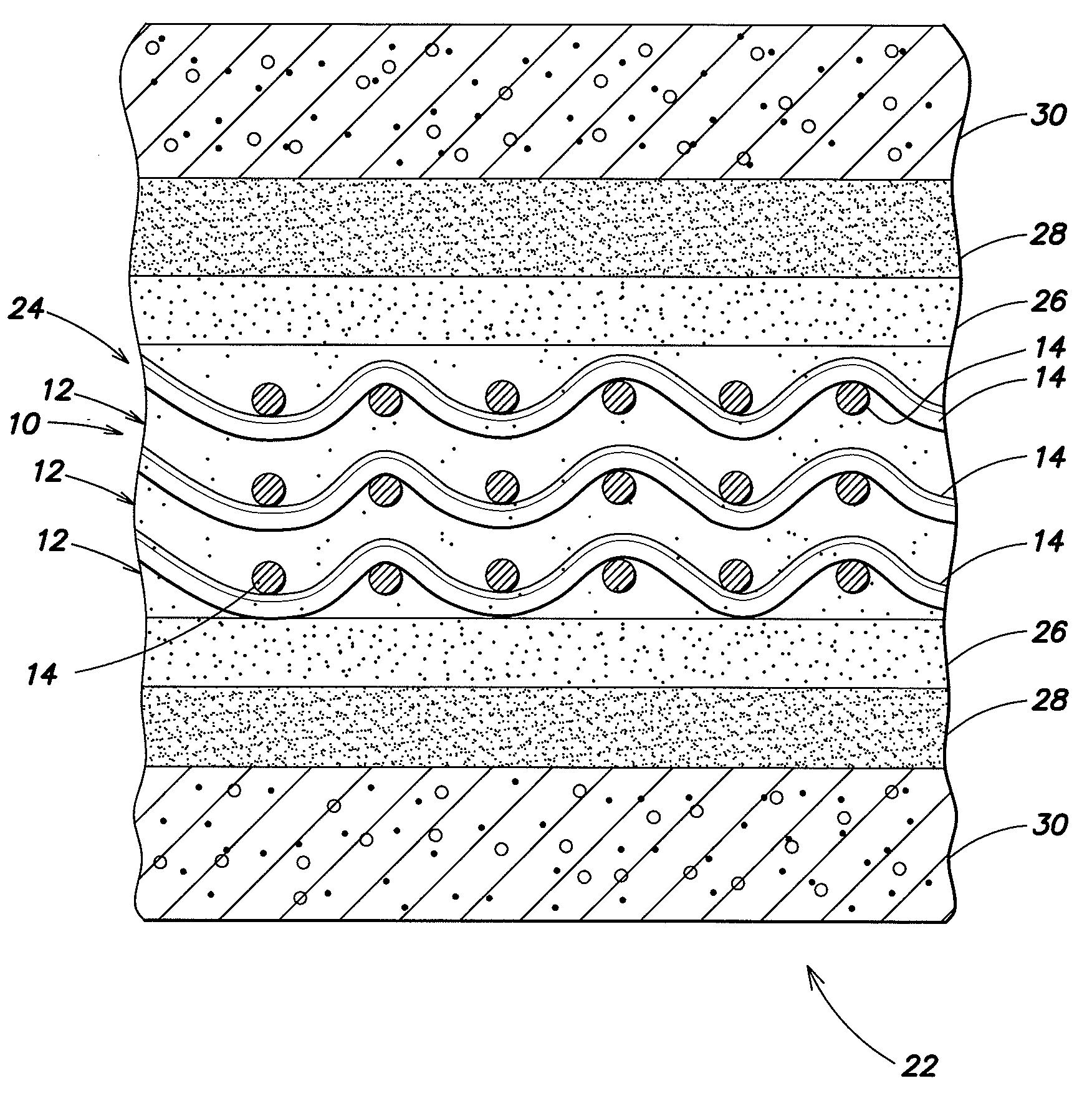
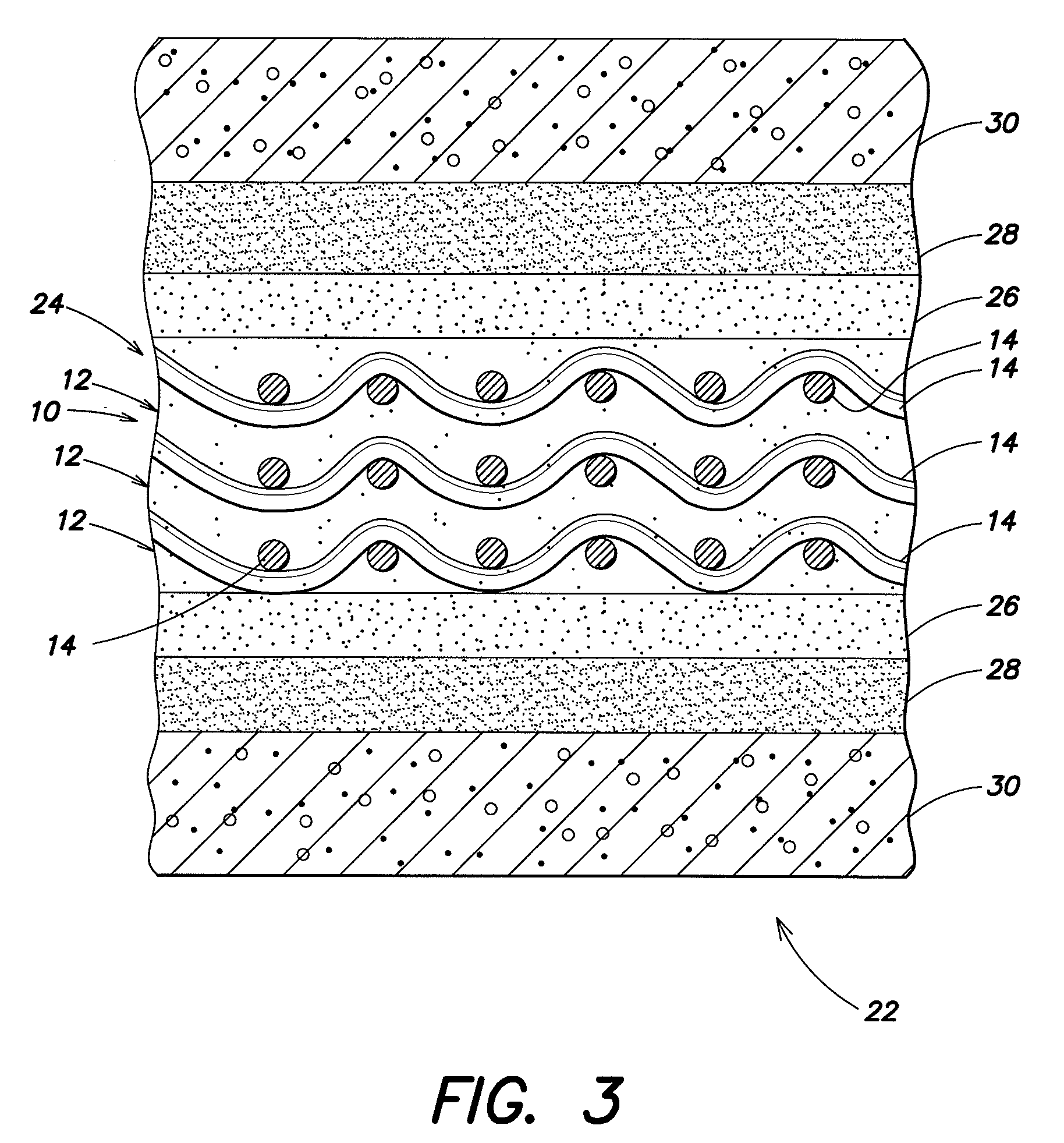
[0013]Referring to FIG. 1, there illustrated is a plan view of a preferred embodiment of a heat generating structure 10 in accordance with the present invention. The structure 10 may comprise at least two constituent portions: a substrate 12 comprised of a plurality of wires 14 of one material, preferably a reactive metal, where the substrate 12 is preferably continuous in all three dimensions; and a coating 16 of a second material, preferably also a reactive metal that is different from the metal comprising the wires 14. The coating 16 is applied on at least a portion of each substrate wire 14 and preferably, on the entirety of each substrate wire 14, to thereby form a substrate 12 of continuously-coated wires 14. Preferably, the three-dimensional structure of the substrate 12 is such that it has an appreciable amount of free volume (i.e., empty space creating voids 18 between crossing wires 14 in the mesh substrate 12). Thus, in FIG. 1 the substrate 12 is preferably a continuous m...


PUM

PropertyMeasurementUnit
temperatureaaaaaaaaaa
diameteraaaaaaaaaa
diameteraaaaaaaaaa

Abstract

A heat generating structure includes a substrate of a first material and a second material coating at least a portion and preferably all of the first material, where the second material is different from the first material. The structure also includes an additional material or compound such as ammonia borane that is impregnated or located within the structure. When the structure is thermally energized, the first and second materials react with each other in an exothermic and self-sustaining reaction that pyrolyzes the impregnated ammonia borane compound to create a target gas, for example, hydrogen from the ammonia borane. An additional material, for example, a thermite, may be interposed between the structure and the ammonia borane to facilitate the ignition of the ammonia borane.

Description

GOVERNMENT RIGHTS[0001]This invention was made with Government support under contract W909MY-06-C-0041 awarded by the U.S. Army. The Government has certain rights in this invention.BACKGROUND OF THE INVENTION[0002]The invention relates in general to heat generating structures, and more particularly to a heat generating structure that provides heat for various purposes, including pyrolysis of various materials or compounds impregnated or located within the structure to generate a desired or target gas.[0003]Fuel cells require hydrogen for proper operation. One proposed source of hydrogen is through the pyrolysis of ammonia borane using a heat source in pellet form. This net exothermic process involving ammonia borane is useful as a source of hydrogen because of its relatively high hydrogen content—ammonia borane is approximately twenty percent by weight hydrogen. Typically, heating of the ammonia borane occurs at a steady rate to achieve the desired pyrolytic decomposition temperatur...

Claims


Application Information

Patent Timeline
Patent Type & Authority Applications(United States)
IPC IPC(8): C06B45/14C01B32/50
CPCC01B3/04C01B13/0203C01B13/0211C01B13/0218Y02E60/364C06B45/14C06C5/06C09K5/18C06B45/00Y02E60/36Y02P20/10
Inventor KELLETT, RICHARD M.MALLERY, JR., CARL F.KORCSMAROS, ROBERT B.
Owner ENSIGN BICKFORD AEROSPACE & DEFENSE
Why Eureka
Try Eureka