
Method of controlling a wind turbine connected to an electric utility grid

a technology of electric utility grid and wind turbine, which is applied in the direction of wind turbine control, motors, emergency control, etc., can solve the problems of affecting the profitability of wind turbines, disconnecting wind turbines require a period of time before they can be connected, and the voltage variation may increase in size or duration, so as to reduce the strain and reduce the dc link voltage

Active Publication Date: 2009-03-26
VESTAS WIND SYST AS
View PDF14 Cites 75 Cited by
  • Summary
  • Abstract
  • Description
  • Claims
  • Application Information

AI Technical Summary

Benefits of technology

[0011]Hereby, is a method established which does not include the above-mentioned disadvantages. It is advantageous that the method allows a more flexible control of the protection means during grid failures where a vast number of different approaches may be chosen in dealing with the grid failure and the exact consequences hereof.
[0027]In an aspect of the invention, said at least two units of said power converter are positioned in a distance from each other e.g. in different positions of the nacelle. Hereby it is possible to level out the heat influence from the different units as well as minimize the size of any necessary cooling means for each unit.

Problems solved by technology

A problem with the grid disconnection of the wind turbines is the fact that the voltage variation may increase in size or duration by the loss of electric power production from the wind turbine generators.
Further, the disconnected wind turbines require a period of time before they can be connected to the utility grid again.
The disconnection of the wind turbines affects the production of power from the wind turbines and thus their profitability.
However, a modern variable speed wind turbine may sustain damaged when the voltage of the utility grid suddenly disappears and it is not disconnected from the grid.
Damage may sustained by a rapid raising voltage at the rotor side of the wind turbine generator or in the frequency converter.
Further damage may be inflicted on the wind turbine when the grid voltage returns due to the flow of large currents and especially to the frequency converter.

Method used


Image

  • Method of controlling a wind turbine connected to an electric utility grid
  • Method of controlling a wind turbine connected to an electric utility grid
  • Method of controlling a wind turbine connected to an electric utility grid

Examples


Embodiment Construction

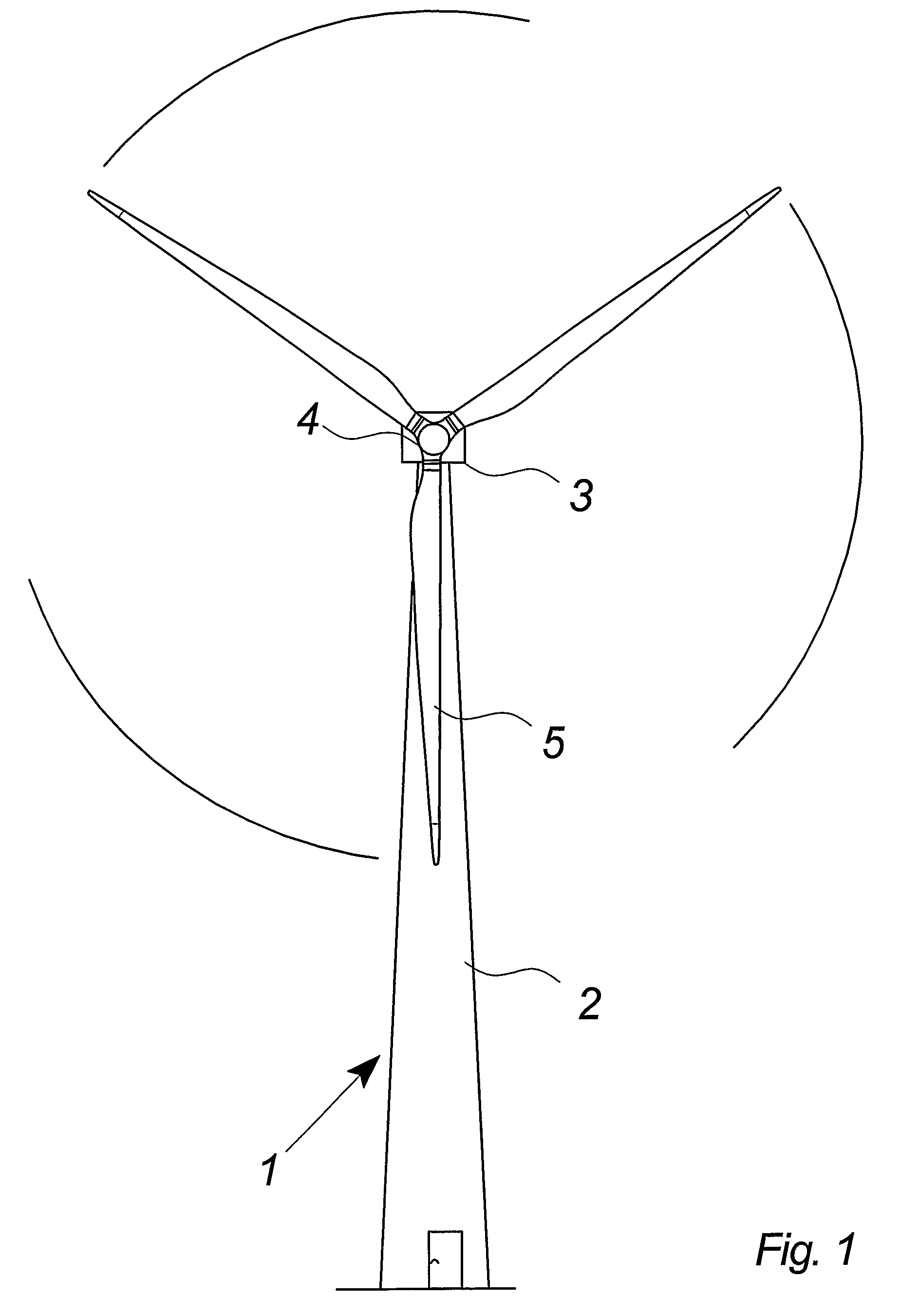
[0037]FIG. 1 illustrates a modern wind turbine 1 with a tower 2 and a wind turbine nacelle 3 positioned on top of the tower. The wind turbine rotor 5, comprising three wind turbine blades, is connected to the nacelle through the low speed shaft that extends out of the nacelle front.

[0038]As illustrated in the figure, wind beyond a certain level will activate the wind turbine rotor due to the lift induced on the blades and allow it to rotate in a perpendicular direction to the wind. The rotation movement is converted to electric power, which is supplied to the utility grid.

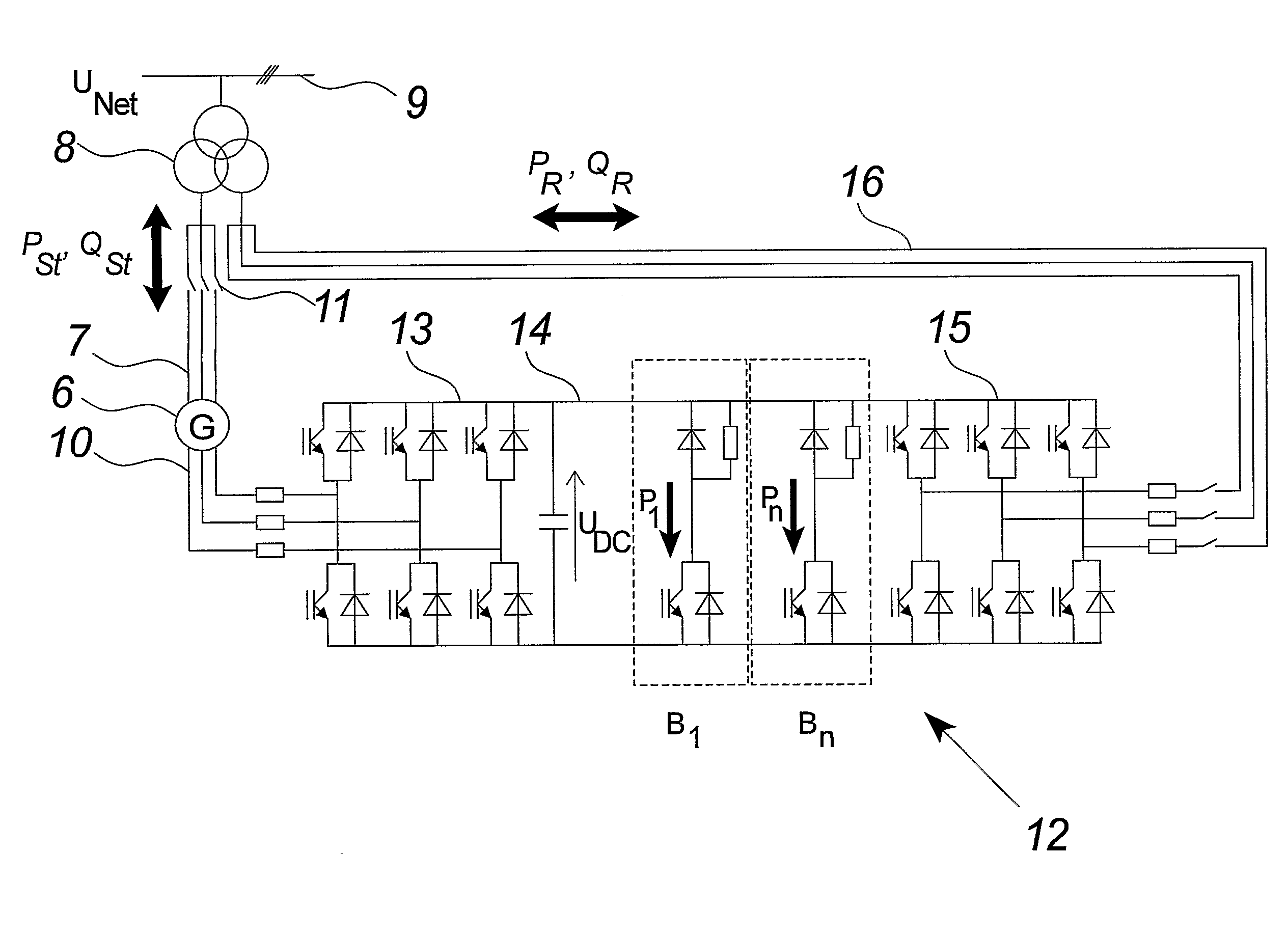
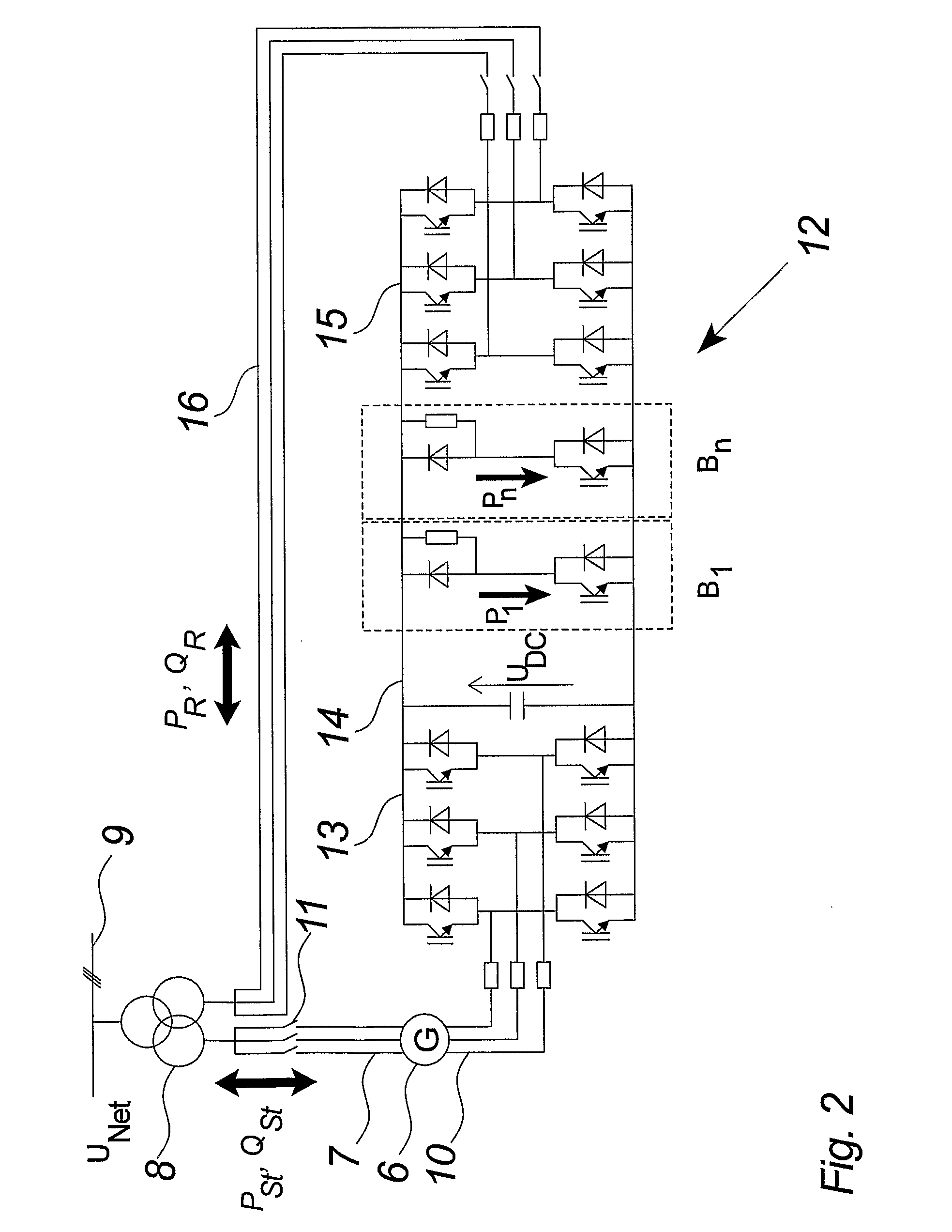
[0039]FIG. 2 illustrates a preferred embodiment of a variable speed wind turbine comprising a doubly fed electric induction generator 6 and a frequency and power converter 12 connected to the rotor of the generator.

[0040]The electric generator 6 comprises a stator 7, connected to the utility grid through disconnection switches 11 and the three phased transformer 8, and may directly supply power, PSt (active stator ...


PUM


Abstract

The invention relates to a method of controlling a wind turbine connected to an electric utility grid during malfunction in said electric utility grid (9). The method comprises the steps of detecting a malfunction in said electric utility grid and operating at least two control units of said power converter (12) in relation to at least one power converter limit value. The invention also relates to a control system for a wind turbine connected to a utility grid and a wind turbine.

Description

BACKGROUND OF THE INVENTION[0001]The invention relates to a method of controlling a wind turbine connected to an electric utility grid during malfunction in said electric utility grid, a control system according to the preamble of claim 10 and a wind turbine according to the preamble of claim 15.DESCRIPTION OF THE RELATED ART[0002]Typically, wind turbines are connected to an electric utility grid in order to be able to generate and supply electric power to consumers located remotely from the wind turbines. The power is sent through the transmission or distribution lines of the utility grid to the consumers.[0003]Wind turbines and other utility grid connected electric power generating means are generally protected from malfunctions in the utility grid by grid disconnection switches. The switches disconnect the wind turbines from the utility grid at the detection of the malfunction. The malfunction may be defined as grid variations above some specific limit e.g. voltage drops above + / ...

Claims


Application Information

Patent Timeline
IPC IPC(8): F03D9/00H02P9/10
CPCF03D7/0272F03D9/003H02P2101/15H02P9/105Y02E10/723F05B2270/107F03D9/255H02M5/458H02M1/0096Y02E10/72Y02E10/76
Inventor NIELSEN, JOHN GODSKESBENSEN, CLAUS
Owner VESTAS WIND SYST AS
Learn More