Organic electroluminescence device

a technology of electroluminescence device and complex compound, which is applied in the direction of luminescence screen of discharge tube, platinum organic compound, organic chemistry, etc., can solve the problems of insufficient devices, insufficient luminescence quantum efficiency, and inability to meet the requirements of high efficiency and high durability. achieve good light emission properties (emission wavelength, luminance, quantum yield, driving voltage) and durability

Active Publication Date: 2009-03-26
UDC IRELAND
View PDF8 Cites 93 Cited by
  • Summary
  • Abstract
  • Description
  • Claims
  • Application Information

AI Technical Summary

Benefits of technology

[0007]An object of the present invention is to provide a metal complex compound having good light emission properties (emission wavelength, luminance, quantum yield, and driving voltage) and durability; and an organic electroluminescence device containing the compound.

Problems solved by technology

Iridium complexes and platinum complexes are known as the phosphorescent material (refer to, for example, U.S. Pat. No. 6,303,238 and International Patent Publication No. 00 / 57676), but development of devices satisfying both high efficiency and high durability has not yet led to success.
These devices are however insufficient from the viewpoint of luminescence quantum efficiency, driving voltage, consumption power, and durability and are required to be improved further by specifying the structure of the platinum complex.

Method used


Image

  • Organic electroluminescence device
  • Organic electroluminescence device
  • Organic electroluminescence device

Examples


example 1

[0239]In a similar manner to Comparative Example 1 except for the use of Compound (31) of the invention (emission wavelength: 480 nm) instead of Comparative compound 1, an organic EL device of Example 1 is fabricated. When a DC constant voltage (7V) is applied to the organic EL device thus fabricated, bluish green light emission is observed. At the same luminance, the voltage of the organic EL device of Example 1 is 0.95 time of that of Comparative Example 1, 0.9 time of that of Comparative Example 2, and 0.89 time of that of Comparative Example 3. The external quantum efficiency of the organic EL device of Example 1 is 1.2 times of that of Comparative Example 1, 1.5 times of that of Comparative Example 2, and 1.2 times of that of Comparative Example 3. The luminance half-life of each of the organic electroluminescence devices thus obtained is determined by setting the device in “OLED Test System Model ST-D” manufactured by Tokyo Systems Development and driving it in a constant curr...

example 2

[0240]In a similar manner to Comparative Example 1 except for the use of Compound (20) of the invention (emission wavelength: 445 nm) instead of Comparative Compound 1, an organic EL device of Example 2 is fabricated. When a DC constant voltage (7V) is applied to the organic EL device thus fabricated, blue light emission is observed. At the same luminance, the voltage of the organic EL device of Example 1 is 0.95 time that of Comparative Example 1, 0.9 time of that of Comparative Example 2, and 0.89 time of that of Comparative Example 3. The external quantum efficiency of the organic EL device of Example 2 is 1.1 times that of Comparative Example 1, 1.4 times that of Comparative Example 2 and 1.2 times of that of Comparative Example 3. The luminance half-life of the organic electroluminescence device thus obtained is determined by setting the device in “OLED Test System Model ST-D” manufactured by Tokyo Systems Development and driving it in a constant current mode under the conditio...


PUM

PropertyMeasurementUnit
thicknessaaaaaaaaaa
thicknessaaaaaaaaaa
transmittanceaaaaaaaaaa

Abstract

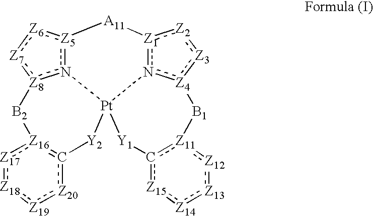
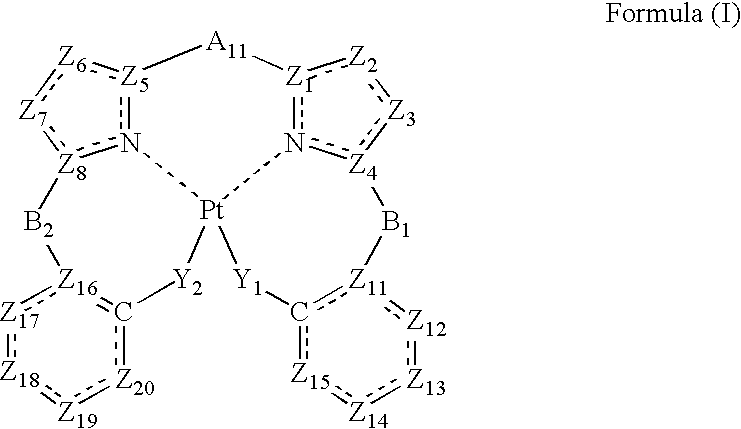
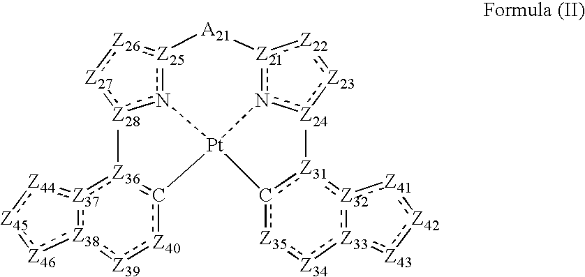
A compound is represented by the following formula (I):
wherein N represents a nitrogen atom; C represents a carbon atom; Pt represents a platinum atom; Z1, Z4, Z5, and Z8 represent a carbon atom or a nitrogen atom; Z2, Z3, Z6, and Z7 represent a carbon atom, a nitrogen atom, an oxygen atom or a sulfur atom; Z11, and Z16 represent a carbon atom or a nitrogen atom; Z12, Z13, Z14, Z15, Z17, Z18, Z19, and Z20 represent a carbon atom, a nitrogen atom, an oxygen atom, or a sulfur atom; Y1 and Y2 represent a single bond, an oxygen atom, a sulfur atom, a nitrogen atom; A11 represents a divalent linking group; B1 and B2 represent a single bond or a divalent linking group.

Description

BACKGROUND OF THE INVENTION [0001]1. Field of the Invention[0002]The present invention relates to a metal complex compound and an organic electroluminescence device containing the compound.[0003]2. Description of the Related Art[0004]Since organic electroluminescence devices (organic EL devices) can provide light emission having high luminance even at a low driving voltage, active research and development on them have been made in recent years. In general, organic EL devices have organic layers including a light emitting layer and a pair of electrodes sandwiching these layers therebetween. Electrons injected from a cathode and holes injected from an anode recombine in the light emitting layer and energy of excitons thus generated is utilized for light emission.[0005]Use of a phosphorescent material has recently accelerated improvement in the efficiency of the device. Iridium complexes and platinum complexes are known as the phosphorescent material (refer to, for example, U.S. Pat. N...

Claims


Application Information

Patent Timeline
Patent Type & Authority Applications(United States)
IPC IPC(8): H01J1/63C07F15/00
CPCC07F15/0086C09K11/06C09K2211/1029C09K2211/1033C09K2211/1037C09K2211/1044H05B33/14C09K2211/1092C09K2211/185H01L51/0072H01L51/0081H01L51/0087H01L51/5016C09K2211/1088H10K85/324H10K85/346H10K85/6572H10K50/11H10K2101/10
Inventor KINOSHITA, IKUOYAGI, KAZUNARIMURAKAMI, TAKESHI
Owner UDC IRELAND
Why Eureka
Try Eureka