Sensor-Equipped Bearing for Wheel

a technology for sensors and bearings, applied in the direction of instruments, force/torque/work measurement apparatus, transportation and packaging, etc., can solve problems such as strain on sensor units, and achieve the effects of reducing rigidity, high accuracy, and detecting strain in stationary members

Active Publication Date: 2009-03-26
NTN CORP
View PDF30 Cites 13 Cited by
  • Summary
  • Abstract
  • Description
  • Claims
  • Application Information

AI Technical Summary

Benefits of technology

[0016]Even when in place of the spacer member that is a separate member, a projection, as a spacer, may be integrally formed around the vehicle body fitting hole in a side face of the stationary member, which confronts the knuckle, and the stationary member is engaged with the knuckle at this projection, effects similar to those afforded by the use of the separate spacer member can be obtained. Also, even when in place of the separate spacer member, a projection, as a spacer, may be provided around a bolt insertion hole in the side face of the knuckle, which confronts the stationary member, and the knuckle is held in contact with the stationary member at this projection, similar effects can be obtained.
[0017]Also, since the sensor mounting member of the sensor unit includes at least two contact fixing portions fixed to the stationary member and at least one recess exists between the neighboring contact fixing portions and the strain sensor is arranged in this recess, a larger strain than that in the stationary member occurs in the place where the strain sensor is arranged. As a result of the rigidity being lowered, and, therefore, the strain in the stationary member can be detected with high accuracy.

Problems solved by technology

When a load acts on the rotatable member as a result of travel of the automotive vehicle, the stationary member undergoes deformation through the rolling elements and this deformation brings about a strain on the sensor unit.

Method used


Image

  • Sensor-Equipped Bearing for Wheel
  • Sensor-Equipped Bearing for Wheel
  • Sensor-Equipped Bearing for Wheel

Examples


Embodiment Construction

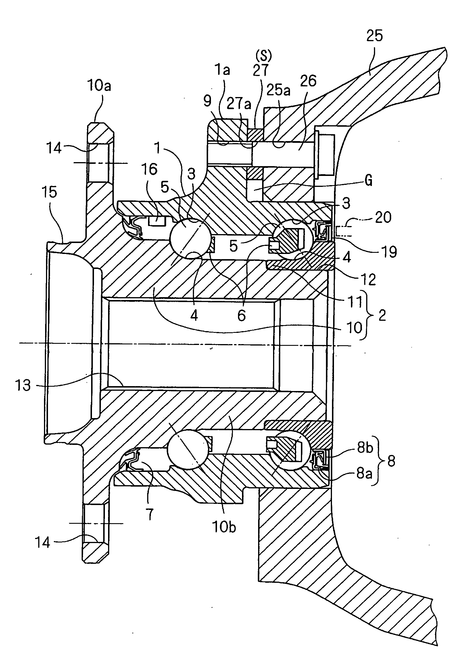
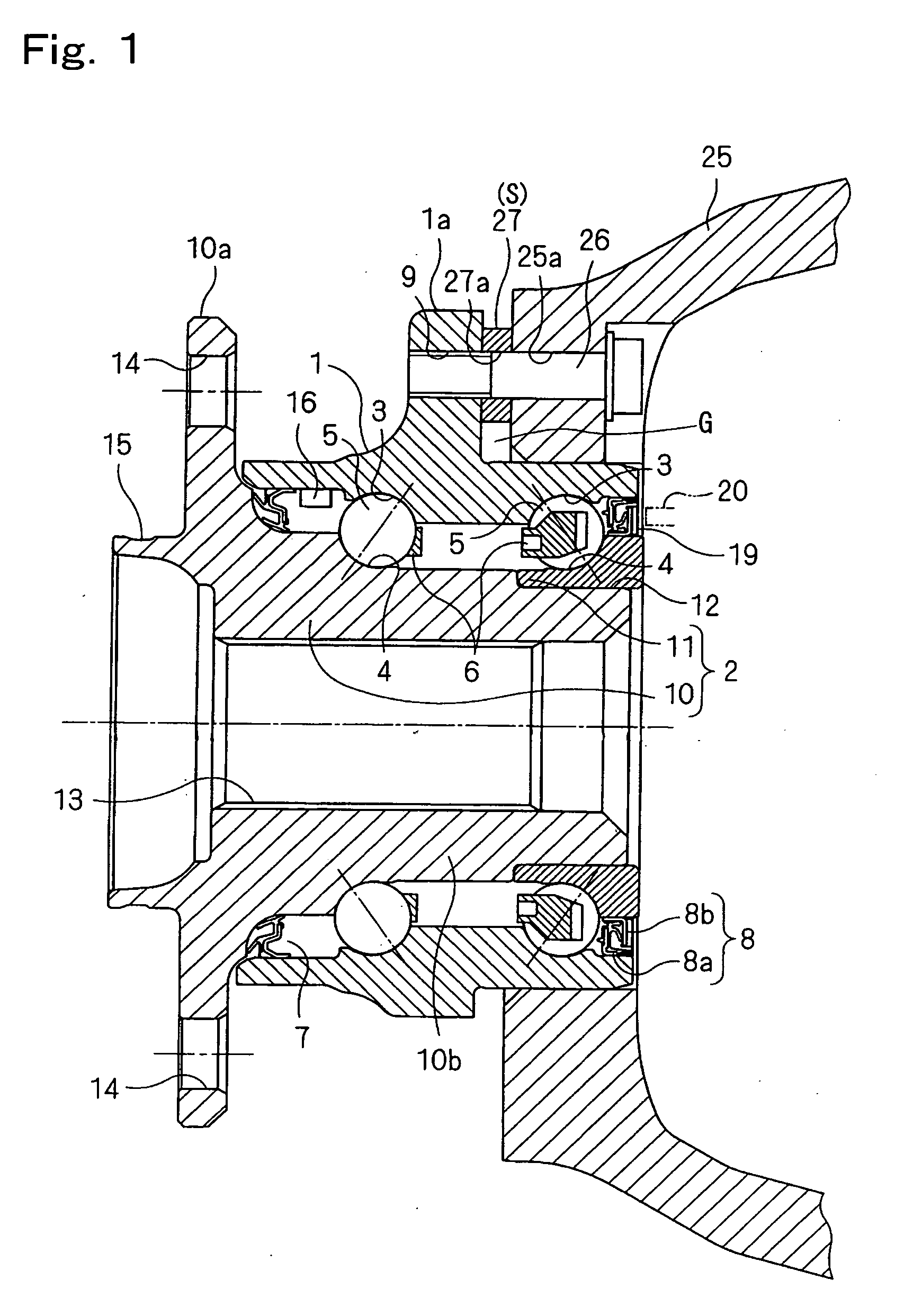
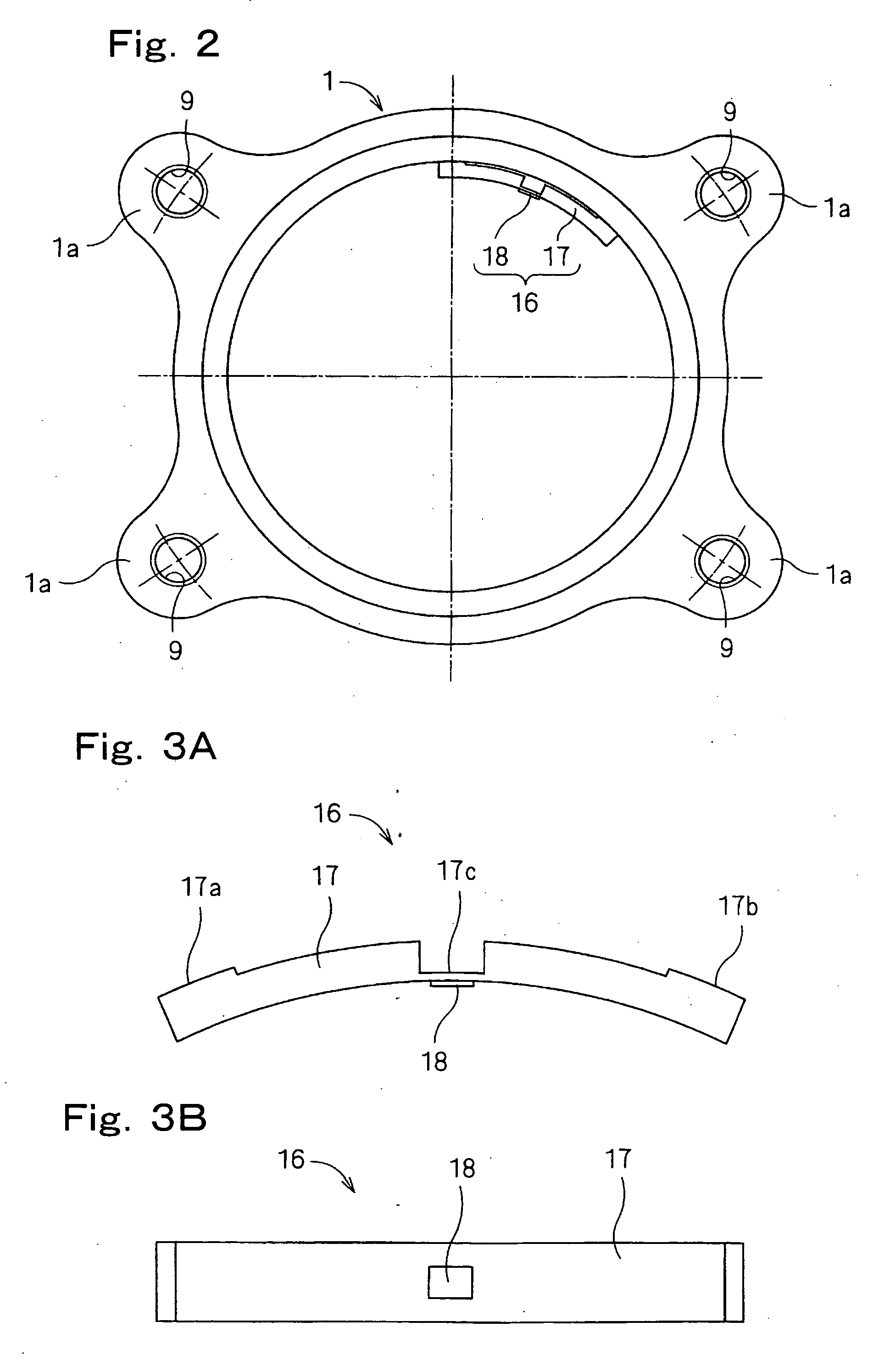
[0034]The first preferred embodiment of the present invention will now be described with particular reference to FIGS. 1 to 3. This embodiment is applied to a wheel support bearing assembly for rotatably supporting a vehicle drive wheel, which is an inner ring rotating model of a third generation type. It is to be noted that in the specification herein set forth, the term “outboard” is intended to mean one side of an automotive vehicle body away from the longitudinal center of the automotive vehicle body, whereas the term “inboard” is intended to mean the opposite side of the automotive vehicle body close towards the longitudinal center of the automotive vehicle body.

[0035]The illustrated wheel support bearing device includes an outer member 1 having an inner periphery formed with a plurality of rows of raceway surfaces 3, an inner member 2 having an outer periphery formed with raceway surfaces 4 formed in face-to-face relation with those raceway surfaces 3, and a plurality of rows ...


PUM


Abstract

In a wheel support bearing assembly having rows of rolling elements (3) interposed between an outer member (1) and an inner member (2), spacers (27) are interposed between vehicle body fitting holes (9) in the outer member (1), which is a stationary member, and a knuckle (25). A sensor unit (16) including a sensor mounting member (17) and a strain sensor (18) is fitted to the outer member (1). The sensor mounting member (17) has at least two contact fixing portions (17a, 17b) fixed to the outer member (1) and, also, has at least one recess (17c) between the neighboring contact fixing portions (17a, 17b), the strain sensor (18) being disposed in this recess (17c).

Description

BACKGROUND OF THE INVENTION[0001]1. Field of the Invention[0002]The present invention relates to a sensor equipped wheel support bearing assembly having incorporated therein a sensor for detecting a load imposed on a bearing area of a vehicle wheel.[0003]2. Description of the Prior Art[0004]For safety travel of an automotive vehicle, the wheel support bearing assembly equipped with a sensor for detecting the rotational speed of one of automotive wheels has hitherto been well known in the art. While the automobile traveling safety precaution is hitherto generally taken by detecting the rotational speed of wheels, it is not sufficient with only the rotational speed of the wheels and, therefore, it is required to achieve a control for safety purpose with the use of other sensor signals.[0005]In view of this, it may be contemplated to achieve an attitude control based on a load acting on each of wheels during travel of an automotive vehicle. By way of example, a large load acts on the o...

Claims


Application Information

Patent Timeline
Patent Type & Authority Applications(United States)
IPC IPC(8): F16C41/00F16C19/28
CPCB60B27/00B60B27/0005B60B27/0068F16C19/522F16C19/186G01L5/0019F16C2326/02B60B27/0094F16C41/00F16C2233/00
Inventor OZAKI, TAKAYOSHIISHIKAWA, TOMOMINISHIKAWA, KENTAROU
Owner NTN CORP
Why Eureka
Try Eureka