Clean bench and method of producing raw material for single crystal silicon

Active Publication Date: 2009-03-26
MITSUBISHI MATERIALS CORP
View PDF1 Cites 22 Cited by
  • Summary
  • Abstract
  • Description
  • Claims
  • Application Information

AI Technical Summary

Benefits of technology

[0019]According to the above described methods for producing a raw material for single crystal silicon, particle can be removed by ionized clean air f

Problems solved by technology

Thus, the particle cannot be removed by the flow of cle

Method used


Image

  • Clean bench and method of producing raw material for single crystal silicon
  • Clean bench and method of producing raw material for single crystal silicon
  • Clean bench and method of producing raw material for single crystal silicon

Examples


Example

[0025]Embodiments of the present invention will now be described with reference to the drawings.

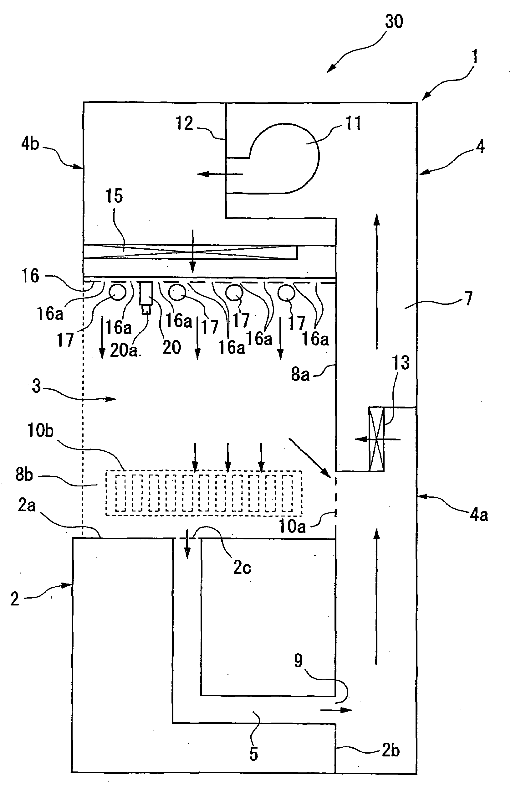
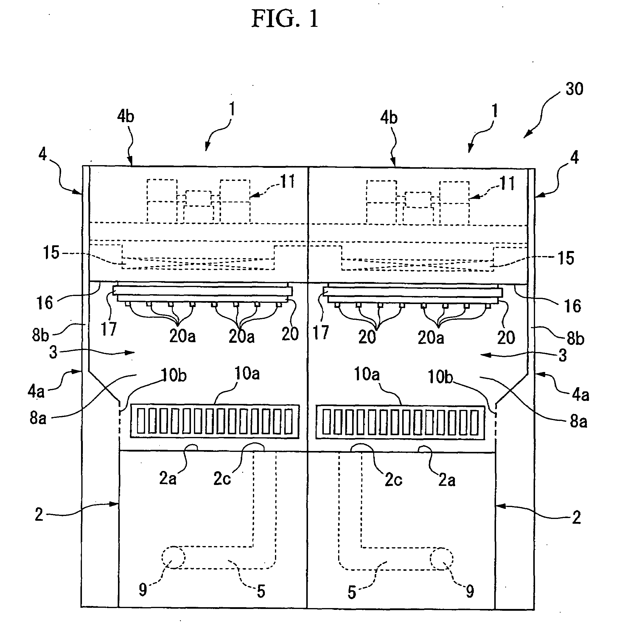
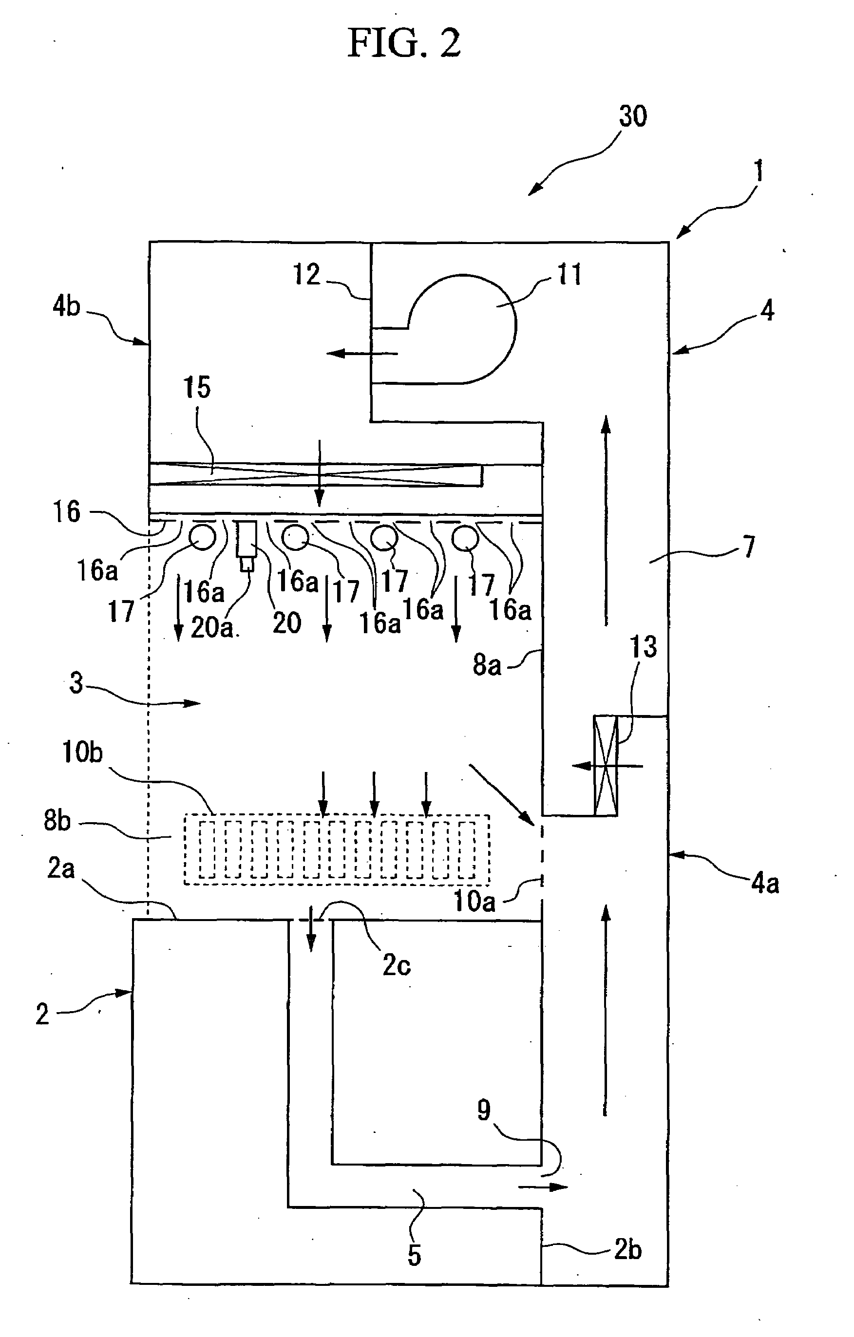
[0026]FIG. 1 is a front view of a clean bench unit according to an exemplary embodiment of the present invention, and FIG. 2 is a lateral cross-sectional view to illustrate the flow of air in the clean bench unit. A clean bench unit 30, as shown in FIG. 1, includes two clean benches 1 provided side by side which have component parts symmetrically provided therein to each other. Each of the clean benches 1 schematically includes a worktable 2 above which a working space 3 is provided and a box (box part) 4. The box 4 includes a side plate 8a disposed at the rear side of the worktable 2 and the working space 3 (on the right side in FIG. 2), a side plate 8b disposed opposite to where the two clean benches 1 border each other, and a ceiling plate 16 to cover the upper sides of the side plates 8a and 8b.

[0027]The worktable 2 includes a working area 2a provided horizontally and with a predeter...


PUM

PropertyMeasurementUnit
Diameteraaaaaaaaaa

Abstract

A clean bench comprising a worktable on which polycrystalline silicon is placed, a box part which includes side plates to surround three sides except a front face of a working space above the worktable, and a ceiling plate which covers an upper side of the working space. Supplying holes are formed in the ceiling plate of the box part, which supply clean air onto an upper surface of the worktable. An ionizer is provided, which ionizes the clean air supplied from the supplying holes to the working space and removes static electricity on the worktable. Suction holes are formed in the side plate of the box part, which suction air from the working space.

Description

[0001]Priority is claimed on Japanese Patent Application No. 2007-229211, filed Sep. 4, 2007, and Japanese Patent Application No. 2008-168497, filed Jun. 27, 2008, the contents of which are incorporated herein by reference.BACKGROUND OF THE INVENTION[0002]1. Field of the Invention[0003]The present invention relates to a clean bench used to sort polycrystalline silicon according to size or quality, which is used as a raw material to be melted in producing single crystal silicon, and a method of producing a raw material for single crystal silicon including a process for cleaning the polycrystalline silicon.[0004]2. Description of the Related Art[0005]Generally, in producing polycrystalline silicon for use as a raw material of single crystal silicon, a heated silicon seed rod is exposed to raw gas including chlorosilane gas and hydrogen gas. Polycrystalline silicon is deposited in a cylindrical shape from the silicon seed rod, and crushed into lumps with proper size or cut into rods wi...

Claims


Application Information

Patent Timeline
IPC IPC(8): C01B33/021B01D50/00B08B15/02
CPCY10S55/18C01B33/037
Inventor SAKAI, KAZUHIROMIYATA, YUKIYASU
Owner MITSUBISHI MATERIALS CORP
Why Eureka
Try Eureka