Deposition system for thin film formation

a thin film and deposition system technology, applied in the direction of chemical vapor deposition coating, coating, additive manufacturing apparatus, etc., can solve the problems of large amount of chemical vapor deposition reaction, difficult to avoid some direct reaction of different precursors, relatively insensitive to transport non-uniformities, etc., to achieve the effect of reducing the residence tim

Active Publication Date: 2009-03-26
EASTMAN KODAK CO
View PDF72 Cites 206 Cited by
  • Summary
  • Abstract
  • Description
  • Claims
  • Application Information

AI Technical Summary

Benefits of technology

[0058]It is an advantage of the present invention that it can provide a compact apparatus for atomic layer deposition onto a substrate that is well suited to a number of different types of substrates and deposition environments.
[0059]It is a further advantage of the present invention that it allows operation, in preferred embodiments, under atmospheric pressure conditions.
[0060]It is yet a further advantage of the present invention that it is adaptable for deposition on a web or other moving substrate, including deposition onto a large area substrate.
[0061]It is still a further advantage of the present invention that it can be employed in low temperature processes at atmospheric pressures, which process may be practiced in an unsealed environment, open to ambient atmosphere. The method of the present invention allows control of the gas residence time r in the relationship shown earlier in equation (3), allowing residence time τ to be reduced, with system pressure and volume controlled by a single variable, the gas flow.

Problems solved by technology

In practice, in any system it is difficult to avoid some direct reaction of the different precursors leading to a small amount of chemical vapor deposition reaction.
Self-saturating surface reactions make ALD relatively insensitive to transport non-uniformities, which might otherwise impair surface uniformity, due to engineering tolerances and the limitations of the flow system or related to surface topography (that is, deposition into three dimensional, high aspect ratio structures).
As a general rule, a non-uniform flux of chemicals in a reactive process generally results in different completion times over different portions of the surface area.
However, in spite of its inherent technical capabilities and advantages, a number of technical hurdles still remain.
However, it is difficult to obtain a reliable scheme for introducing the needed series of gaseous formulations into a chamber at the needed speeds and without some unwanted mixing.
In a typical ALD chamber the volume (V) and pressure (P) are dictated independently by the mechanical and pumping constraints, leading to difficulty in precisely controlling the residence time to low values.
Existing ALD approaches have been compromised with the trade-off between the need to shorten reaction times with improved chemical utilization efficiency, and, on the other hand, the need to minimize purge-gas residence and chemical removal times. One approach to overcome the inherent limitations of “pulsed” delivery of gaseous material is to provide each reactant gas continuously and to move the substrate through a region containing each gas in succession.
In these systems, some mechanism must be employed to confine a particular gas to a spatial region in order that the substrate can sample all of the gases during its movement, but the individual mutually reactive gases cannot mix causing undesirable CVD deposition.
While systems such as those described in the '563 Yudovsky and '022 Suntola et al. patents may avoid some of the difficulties inherent to pulsed gas approaches, these systems have other drawbacks.
The complex arrangements of both the gas flow delivery unit of the '563 Yudovsky patent and the gas flow array of the '022 Suntola et al. patent, each providing both gas flow and vacuum, make these solutions difficult to implement, costly to scale, and limit their potential usability to deposition applications onto a moving substrate of limited dimensions.
Moreover, it would be very difficult to maintain a uniform vacuum at different points in an array and to maintain synchronous gas flow and vacuum at complementary pressures, thus compromising the uniformity of gas flux that is provided to the substrate surface.

Method used


Image

  • Deposition system for thin film formation
  • Deposition system for thin film formation
  • Deposition system for thin film formation

Examples


Embodiment Construction

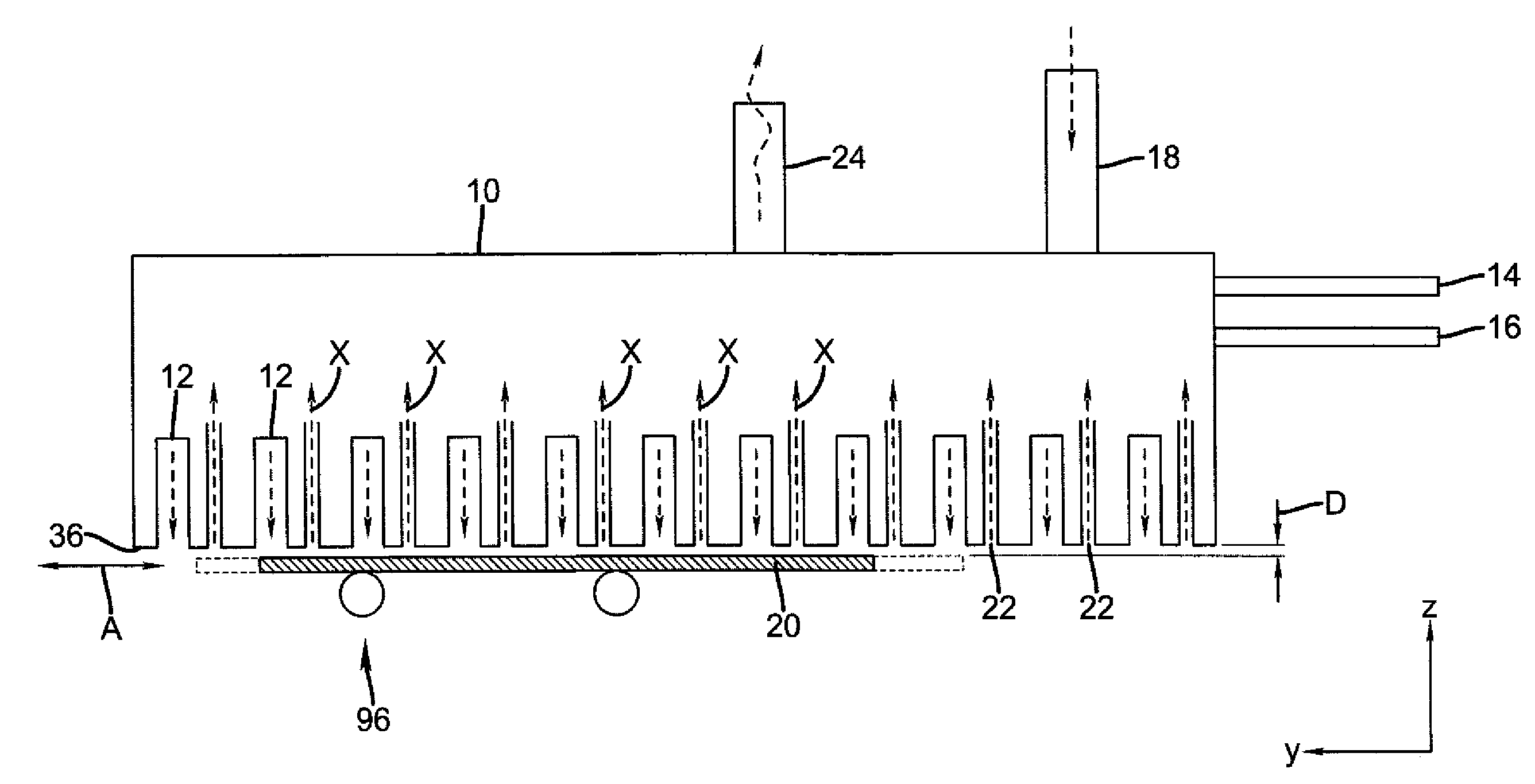
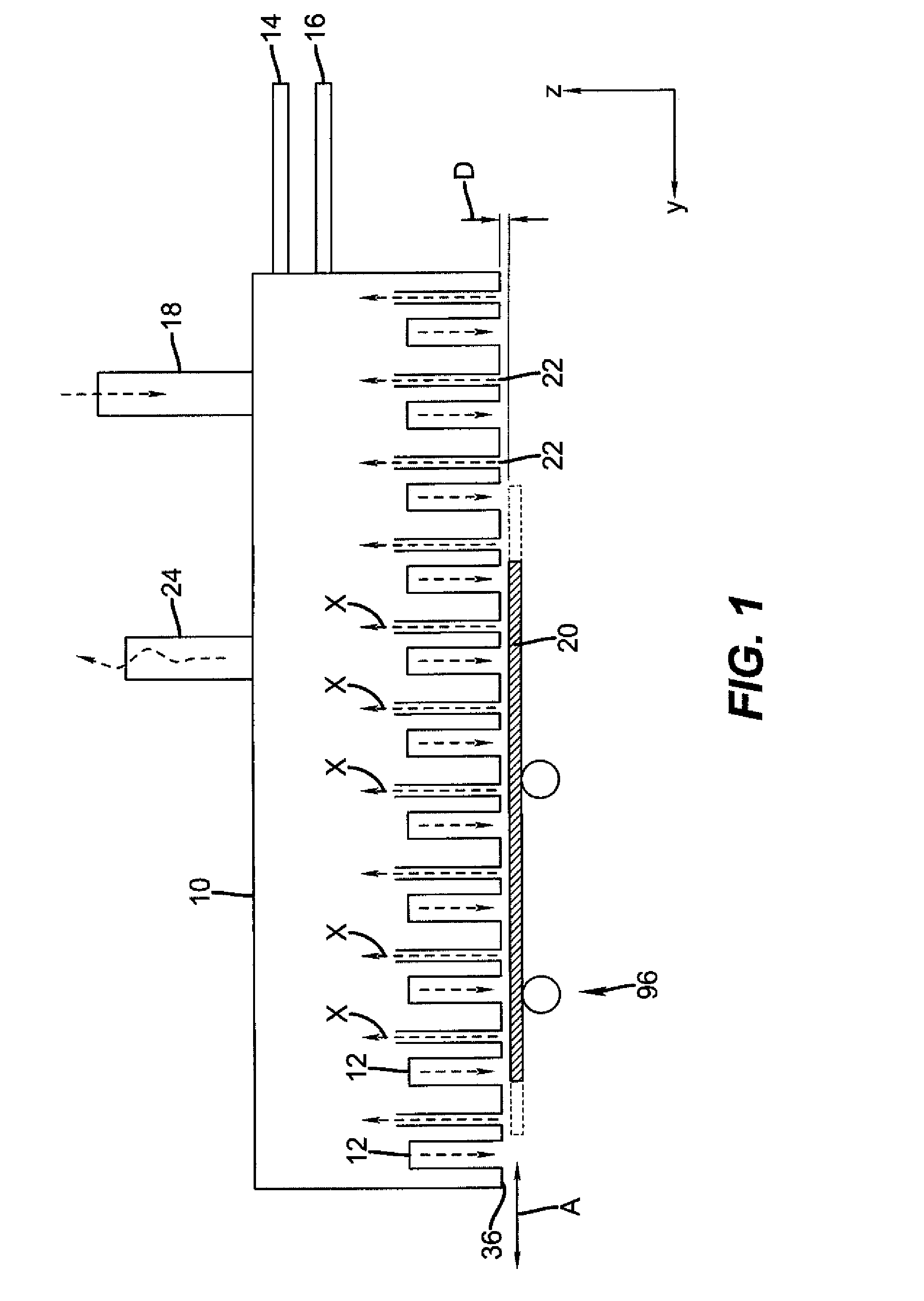
[0095]The present description is directed in particular to elements forming part of, or cooperating more directly with, apparatus in accordance with the invention. It is to be understood that elements not specifically shown or described may take various forms well known to those skilled in the art.

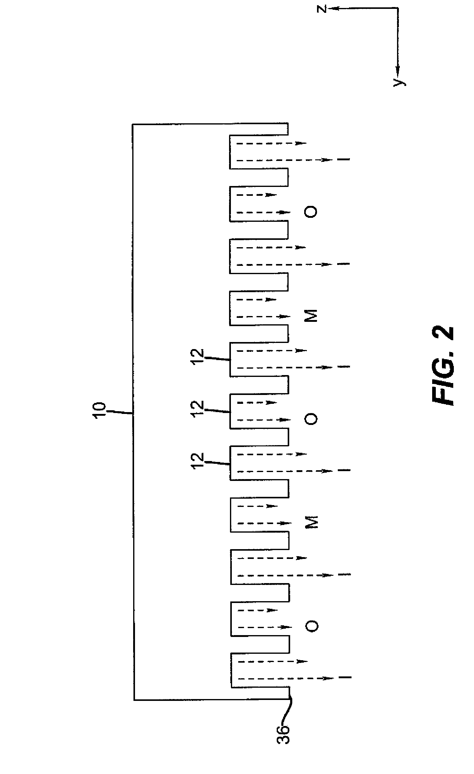
[0096]For the description that follows, the term “gas” or “gaseous material” is used in a broad sense to encompass any of a range of vaporized or gaseous elements, compounds, or materials. Other terms used herein, such as: reactant, precursor, vacuum, and inert gas, for example, all have their conventional meanings as would be well understood by those skilled in the materials deposition art. The figures provided are not drawn to scale but are intended to show overall function and the structural arrangement of some embodiments of the present invention.

[0097]For many thin film applications the substrate is commonly considered as a sheet of material which may or may not be planar. Examples of...


PUM

PropertyMeasurementUnit
separation distanceaaaaaaaaaa
temperatureaaaaaaaaaa
distanceaaaaaaaaaa

Abstract

A process for depositing a thin film material on a substrate is disclosed, comprising simultaneously directing a series of gas flows from the output face of a delivery head of a thin film deposition system toward the surface of a substrate, and wherein the series of gas flows comprises at least a first reactive gaseous material, an inert purge gas, and a second reactive gaseous material, wherein the first reactive gaseous material is capable of reacting with a substrate surface treated with the second reactive gaseous material, wherein one or more of the gas flows provides a pressure that at least contributes to the separation of the surface of the substrate from the face of the delivery head. A system capable of carrying out such a process is also disclosed.

Description

CROSS-REFERENCE TO RELATED APPLICATIONS[0001]The present application is related to U.S. application Ser. No. 11 / 392,007, filed Mar. 29, 2006 by Levy and entitled, “PROCESS FOR ATOMIC LAYER DEPOSITION,” U.S. application Ser. No. 11 / 392,006, filed Mar. 29, 2006 by Levy and entitled “APPARATUS FOR ATOMIC LAYER DEPOSITION,” U.S. application Ser. No. 11 / 620,738, filed Jan. 8, 2007 by Levy and entitled “DELIVERY DEVICE FOR DEPOSITION,” U.S. application Ser. No. 11 / 620,740, filed Jan. 8, 2007 by Nelson et al. and entitled “DELIVERY DEVICE COMPRISING GAS DIFFUSER FOR THIN FILM DEPOSITION,” U.S. application Ser. No. 11 / 620,744, filed Jan. 8, 2007 by Levy and entitled, “DEPOSITION SYSTEM AND METHOD USING A DELIVERY HEAD SEPARATED FROM A SUBSTRATE BY GAS PRESSURE,” U.S. application Ser. No. ______ (docket 94077), filed concurrently herewith by Kerr et al. and entitled, “DEPOSITION SYSTEM FOR THIN FILM FORMATION,” U.S. application Ser. No. ______ (docket 94217), filed concurrently herewith by K...

Claims


Application Information

Patent Timeline
Patent Type & Authority Applications(United States)
IPC IPC(8): H01L21/311C23C16/00
CPCC23C16/45519C23C16/545C23C16/45551B33Y80/00
Inventor LEVY, DAVID H.KERR, ROGER S.CAREY, JEFFREY T.
Owner EASTMAN KODAK CO
Why Eureka
Try Eureka