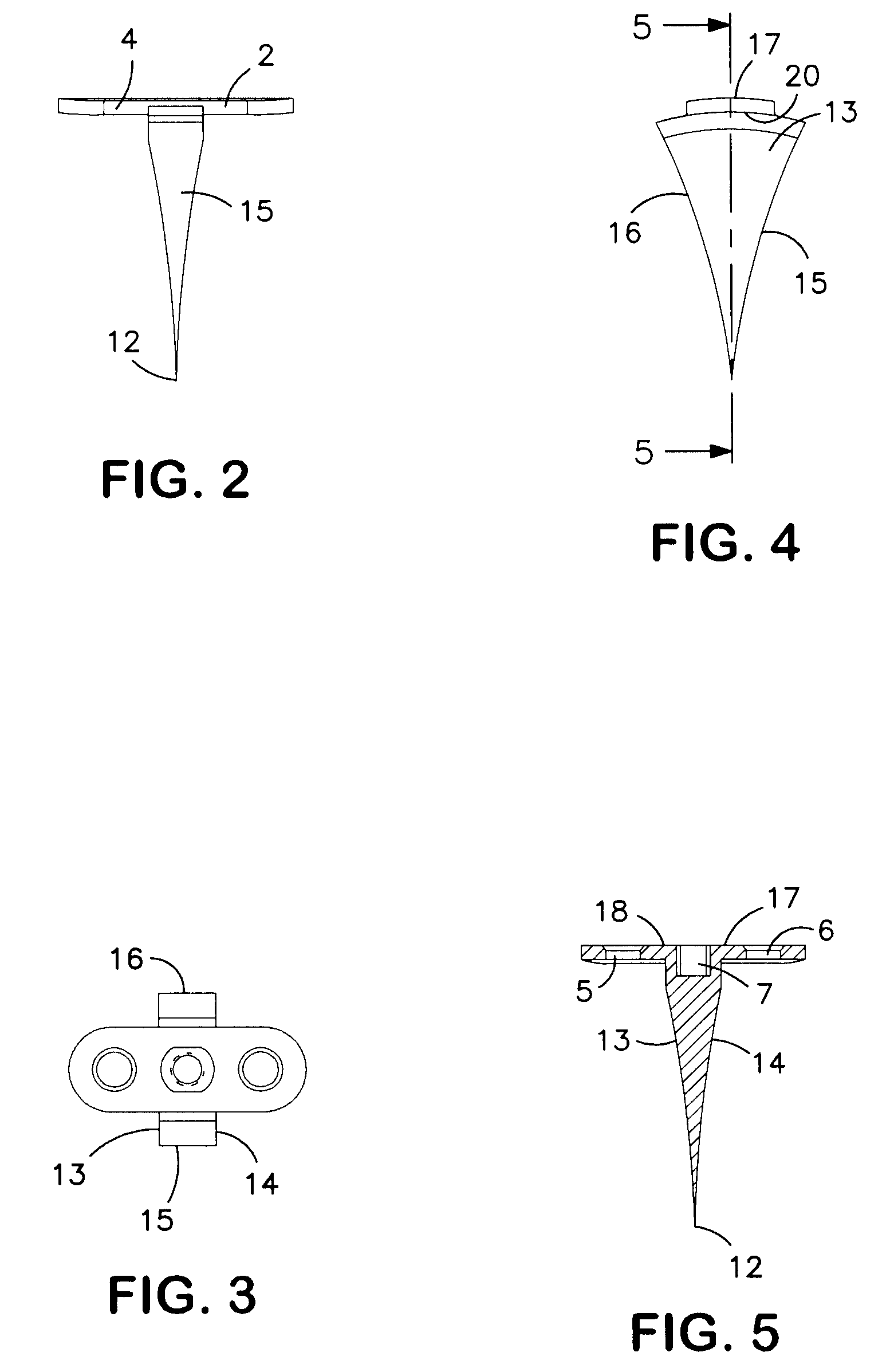
[0005]The underlying idea of the invention is to replace the blunt front side in a known osteotomy wedge by a pointed end section. Providing an end-side sharp wedge section allows the medical foot implant (osteotomy wedge) to be forced directly into a foot bone and thus for an upstream severing step during the operation to be at least partially omitted, on the whole accelerating the operation and thus minimizing the strain for the patient. A particular
advantage of a medical foot implant designed according to the concept of the invention is that depending on the introduction depth of the medical foot implant in a foot bone extensive shattering of the rear
cortical bone of the foot bone can be largely prevented. A medical foot implant designed according to the concept of the invention is suited not only to fixing two adjacent, if needed still partially interconnected or fully separated bone segments at a predetermined
wedge angle relative to one another. Due to its form the medical foot implant can also be forced with a pointed wedge section directly into a tarsometatarsal joint of the foot, preferably into a first tarsometatarsal joint, in particular for treating hallus valgus to stiffen the joint and to fix both adjacent bones at a predetermined
wedge angle relative to one another. The proposed medical foot implant is preferably (fully) designed from a
biocompatible material, preferably
titanium or a
titanium alloy.
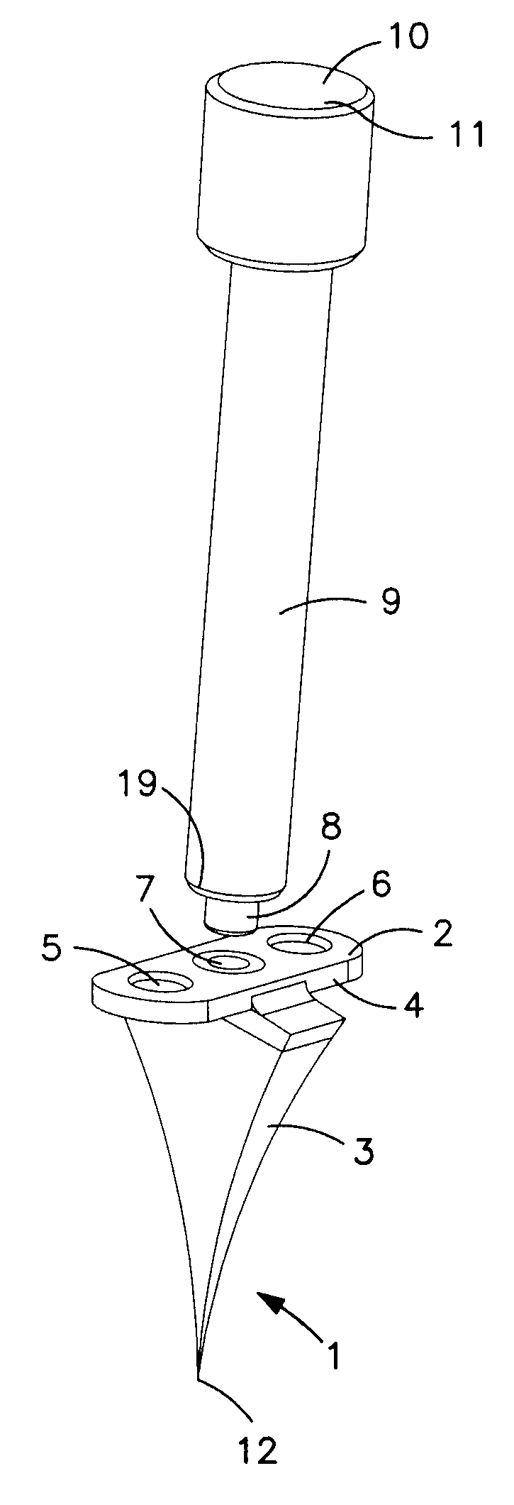
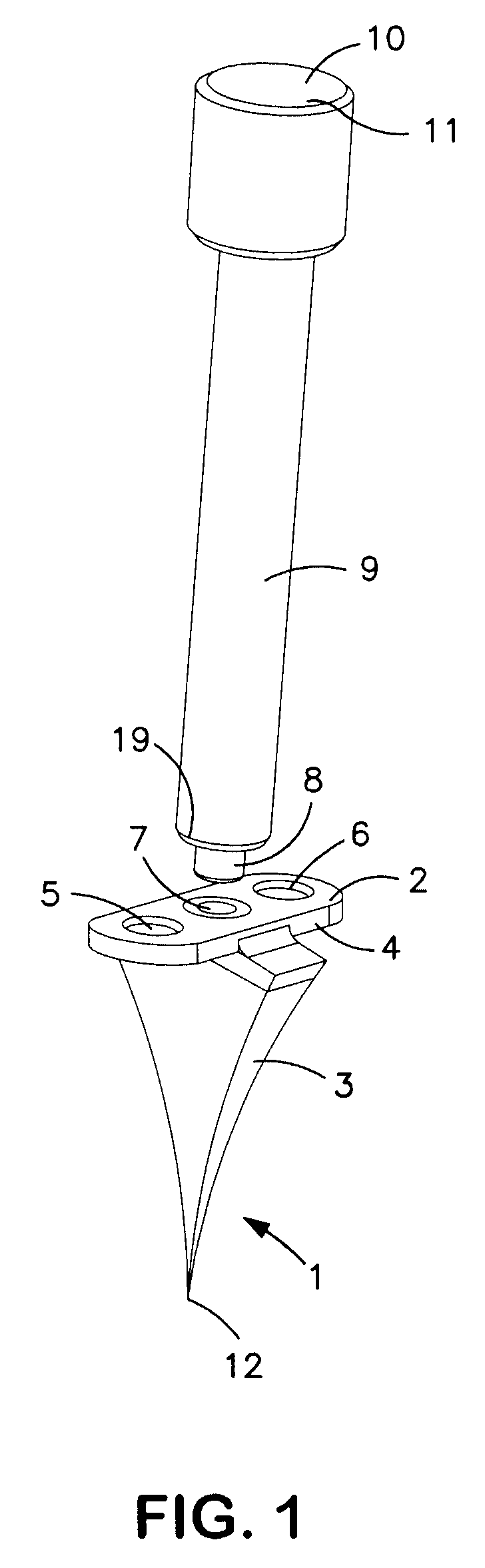
[0012]A further development of the invention advantageously provides that the foot implant is designed such that a forcing aid (forcing pin) can be detachably fixed easily to the latter. The forcing aid can preferably be fixed on the foot implant such that a longitudinal middle axis of the forcing aid aligns with a longitudinal middle axis of the foot implant leading through the end-side tip of the wedge section of the foot implant.
[0013]A thread, preferably an inner thread, can be provided for detachable fixing of a forcing aid on the foot implant in a surprisingly simple manner, whereby the thread, in particular the inner thread, is arranged preferably on a side of the foot implant averted from the tip of the wedge section, in particular in its fastening section.
[0016]A further development of the invention advantageously provides that two side sections averted from one another, i.e. arranged on opposite sides, are of varying sizes transversely to their longitudinal extension, thus have a different width extension in each case at a common height, whereby the width extension of both side sections understandably decreases to the punctiform tip, preferably constantly. This produces a nested
wedge shape, specifically on one side to the punctiform tip and on the other side in a transverse direction thereto, so as to be able to make an angle correction of the bone segments arranged to the side of the osteotomy wedge in two directions accordingly, one in the direction of forcing and the other transversely thereto.
[0017]In other terms, a further development of the invention advantageously provides that two opposite side sections are inclined not only in the direction of their longitudinal extension, i.e. in the direction of the punctiform tip relative to one another, thus arranged at an angle to one another, but also in a transverse direction thereto so as to produce an added wedging effect, specifically transversely to the main wedge direction. In a transverse direction this results in a wedge designed preferably blunt on the end side.
[0021]The invention also promotes a
system for easier introduction (forcing) of the medical foot implant into a bone or into a tarsometatarsal joint of the foot. The
system comprises a previously described foot implant and a forcing aid which can be fixed detachably on the foot implant, preferably designed as a forcing pin. Particularly preferred is an embodiment in which the forcing aid is provided on the end side with an outer thread, which can be screwed into a preferably centrically arranged inner thread of the foot implant, which extends preferably in a longitudinal direction into the wedge section. After the foot implant is forced into a foot bone or into a joint of the foot the forcing aid can be loosened from the foot implant.

