
Traffic control system and traffic control method

a traffic control system and traffic control technology, applied in two-way working systems, instruments, digital computers, etc., can solve the problems of delay in transmission of difference information, increase in difference information, and increase in information stream, so as to control the communication quality of the communication line b, and reduce the amount of streaming data

Inactive Publication Date: 2009-03-26
HITACHI LTD
View PDF4 Cites 22 Cited by
  • Summary
  • Abstract
  • Description
  • Claims
  • Application Information

AI Technical Summary

Benefits of technology

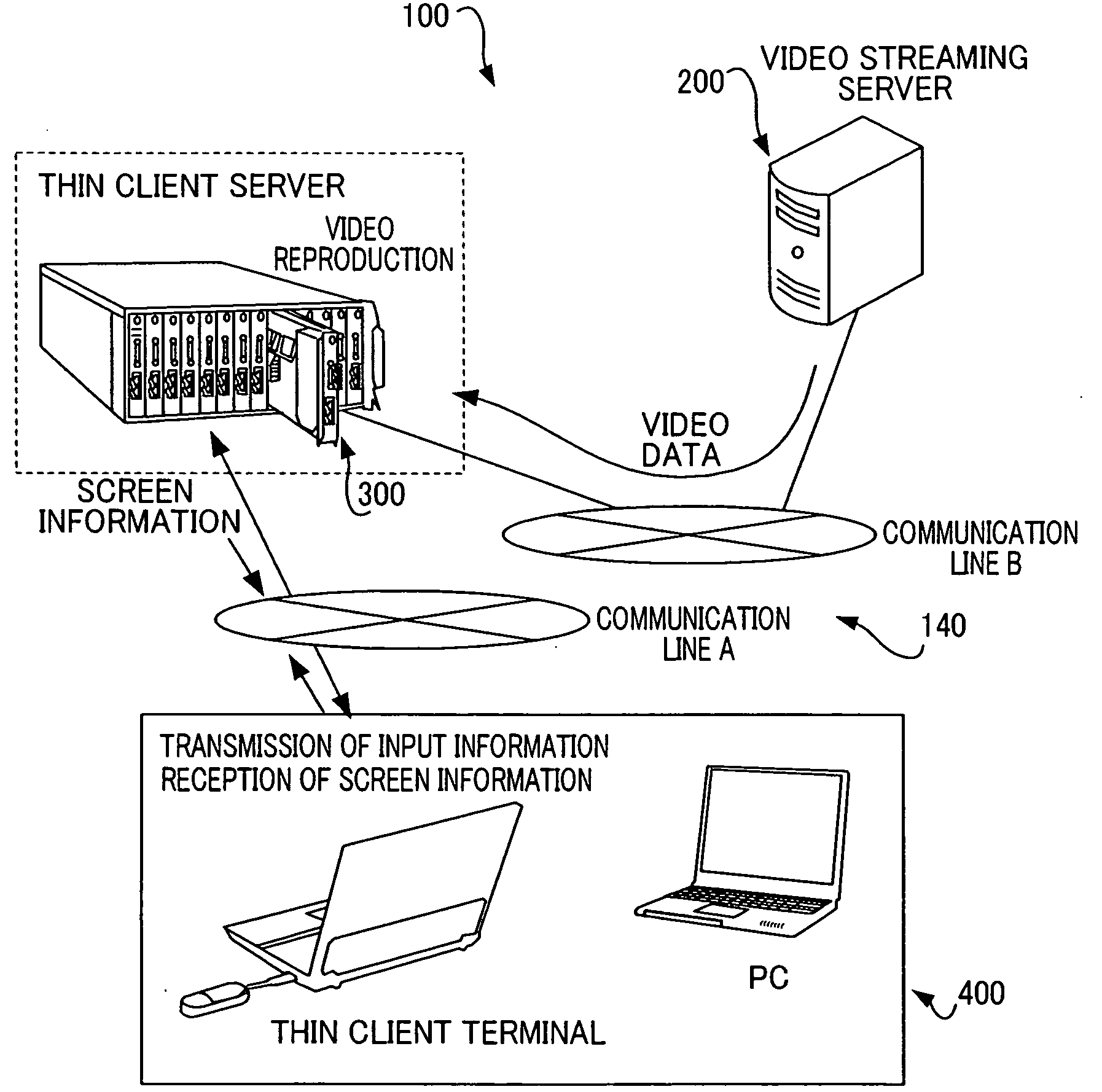
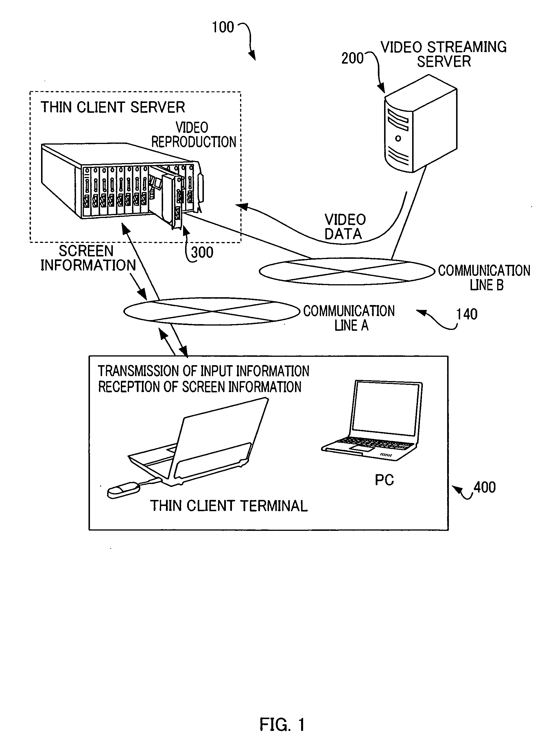
[0008]In order to solve the aforementioned problem, the present invention provides a traffic control system which is an information processing system that controls traffic among a video streaming server, a relay server having a video reproduction program for reproducing video data distributed from the video streaming server, and a client terminal that receives screen information corresponding to the reproduced video data from the relay server and outputs the screen information on a screen, the traffic control system including: a quality measuring unit configured to measure communication quality on a communication line A between the relay server and the client terminal; an upstream specifying unit configured to specify an amount of streaming data, in a communication line B between the video streaming server and the relay server, corresponding to an amount of the screen information of a communication data amount accepted for the measured communication quality a of the communication line A; and an upstream control unit configured to perform control such that an amount of video data distributed to the relay server from the video streaming server via the communication line B can be adjusted to the specified amount of streaming data. This configuration makes it possible to perform control to adjust the amount of video data distributed to the relay server from the video streaming server via the communication line B (upstream) according to communication quality of the communication line A (downstream) and to transmit, to the client, screen information produced during video reproduction by the server according to network quality.
[0017]Moreover, the present invention provides a traffic control method for an information processing system which controls traffic among a video streaming server, a relay server having a video reproduction program for reproducing video data distributed from the video streaming server, and a client terminal that receives screen information corresponding to the reproduced video data from the relay server and outputs the screen information on a screen, the method comprising the information processing system performing quality measuring processing for measuring communication quality on a communication line A between the relay server and the client terminal; and the information processing system performing downstream control processing for performing control such that an amount of screen information transmitted to the client terminal from the relay server via the communication line A can be adjusted to a communication data amount accepted for the measured communication quality a of the communication line A. This makes it possible to perform control to adjust the amount of screen information distributed to the client terminal from the relay server via the communication line A (downstream) according to communication quality of the communication line A (downstream) and to transmit, to the client, screen information produced during video reproduction by the server according to network quality.

Problems solved by technology

Thus, a high screen update frequency results in an increase in the difference information.
For this reason, when the screen update occurs frequently under a circumstance where line quality between the thin client server and the thin client terminal is poor (for example, a small bandwidth, a large transmission delay, and the like), transmission of the difference information is delayed, so that the screen, when seen from the user, looks like it is not updated smoothly.
Moreover, such frequent screen update may cause other problems that congestion occurs in a network, and that traffic even in an uplink (client to server) direction is affected in a half-duplex network (network such as an ADSL or the like where uplink and downlink communication quality is asymmetric), so that data inputted through a mouse or a keyboard is not normally transmitted.
Particularly, these problems appear remarkably under a circumstance where reproduced data of a video image is transmitted to the thin client terminal from the thin client server.
This problem is caused because there is no mechanism with which screen image is transmitted according to the network quality between the server and the client.

Method used


Image

  • Traffic control system and traffic control method
  • Traffic control system and traffic control method
  • Traffic control system and traffic control method

Examples


example 1

Processing Flow Example 1

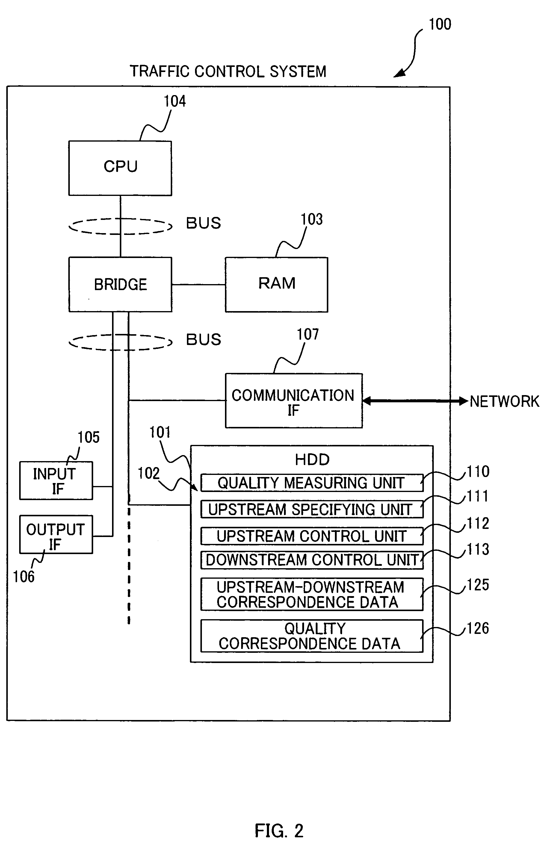
[0066]Descriptions will be given of an actual procedure of a traffic control method of the present embodiment below on the basis of the drawings. It should be noted that the operations corresponding to the traffic control method to be described below are implemented by programs that are read into RAMs of the thin client terminal 400 and the thin client server 300 which are serving as the traffic control system 100 and are executed by the CPU. Moreover, the program is formed of codes for performing various types of operations to be described below. In the present embodiment, descriptions will be given, as an example, on the assumption that the thin client terminal 400 includes the quality measuring unit 110 and the thin client server 300 includes the upstream specifying unit 111, upstream control unit 112, and downstream control unit 113.

[0067]FIG. 7 is a view showing a processing flow example 1 of a traffic control method in the present embodiment. First, th...

example 2

Processing Flow Example 2

[0075]FIG. 8 is a view showing a processing flow example 2 of the traffic control method of the present embodiment. Moreover, as another example, for example, a case where the thin client server 300 includes the downstream control unit 113 can be assumed. In this case, the quality measuring unit 110, which is included in the thin client terminal 400, measures communication quality of the communication line A between the thin client server 300 and the thin client terminal 400 (S200). Further, the quality measuring unit 110 sends data of the measured communication quality a of the communication line A to the downstream control unit 113, which is included in the thin client server 300, via the thin client terminal 400 (S201).

[0076]Meanwhile, the downstream control unit 113 of the thin client server 300 receives data of the communication quality a from the thin client terminal 400 (S202) and stores it in the RAM 303 (S203). Subsequently, the downstream control u...


PUM


Abstract

A traffic control system 100 includes: a quality measuring unit 110 that measures communication quality on a communication line A between a relay server 300 and a client terminal 400; an upstream specifying unit 111 that specifies an amount of streaming data, in a communication line B between a video streaming server 200 and the relay server 300, corresponding to an amount of screen information of a communication data amount accepted for the measured communication quality a of the communication line A; and an upstream control unit 112 that performs control such that an amount of video data to be distributed to the relay server 300 from the video streaming server 200 via the communication line B can be adjusted to the specified amount of streaming data.

Description

INCORPORATION BY REFERENCE[0001]This application claims priority based on a Japanese patent application, No. 2007-226566 filed on Aug. 31, 2007, the entire contents of which are incorporated herein by reference.BACKGROUND OF THE INVENTION[0002]The present invention relates to a traffic control system and a traffic control method, and more particularly relates to a technique for managing video streaming in different communication lines according to quality of each communication line, the different communication lines being respectively used for coupling between a video streaming server and a relay server (thin client server) receiving streaming data from the video streaming server, and coupling between the relay server and a client terminal (thin client terminal) receiving the reproduced streaming data from the relay server.[0003]Streaming contents such as videos are likely to impose a heavy load on a network. Thus, there is a need to perform an appropriate distribution management ac...

Claims


Application Information

Patent Timeline
Patent Type & Authority Applications(United States)
IPC IPC(8): G06F15/16H04L47/2475H04L47/724H04L47/80H04N7/173H04N21/222H04N21/2381H04N21/24H04N21/61H04N21/647
CPCH04L47/10H04L47/12H04L47/2416H04L65/80H04L65/605H04L65/4092H04L47/25H04L65/613H04L65/765H04L65/756
Inventor SAITO, HIROSHIHAYASHI, SHINICHIOGAWA, YUKIOKIMURA, YUJISABUCHI, TAKAHIDE
Owner HITACHI LTD
Learn More