Irrigation tire

a technology of irrigation tires and tires, which is applied in the field of tires, can solve the problems of shortening the installation time of tires and wheels for agricultural apparatuses, uncomfortable and turbulent movement to vehicles, and vehicles that spend any significant amount of time moving forward and backward, so as to increase the traction performance and cleaning ability of tires, uniform resistance, and increase the crown strength of tires

Active Publication Date: 2009-04-02
BRIDGESTONE AMERICAS TIRE OPERATIONS LLC
View PDF72 Cites 35 Cited by
  • Summary
  • Abstract
  • Description
  • Claims
  • Application Information

AI Technical Summary

Benefits of technology

[0018]Also included is a non directional pneumatic tire used to support an agricultural irrigation system. The tire includes a raised tread pattern having a substantially centrally positioned circumferential lug and longitudinal lugs circumferentially positioned parallel to the axis of the tire. The longitudinal lugs preferably extend from the side walls of the tire towards the circumferential lug and include a terminal end positioned on the circumferential lug. The circumferential lug and terminal ends of the longitudinal lugs preferably provide a substantially uniform resistance between the tire and the surface upon which the tire rolls when the tire is rotated in opposite directions.
[0019]The circumferential lug and longitudinal lugs can also be positioned to increase the crown strength of the tire and to increase the traction performance and cleaning ability of tire. Additionally, the tread design can be designed such that there is a reduced contact pressure between the tire and the surface upon which it traverses.

Problems solved by technology

These prior art tires have several drawbacks for vehicles that spend any significant amount of time moving in both forward and backward directions.
For example, these prior art tires result in an uncomfortable and turbulent movement to the vehicle supported by those prior art tires when moved in a reverse direction.
A majority of this turbulence is due to the specific tread pattern on these prior art tires and the orientation of the various elements, commonly referred to as lugs, on the tread pattern.
A substantial portion of agricultural devices, such as tractors, trailers, crop planting devices, crop harvesting devices, and the like, are used in locations, such as agricultural fields, when it is undesirable for the agricultural device to substantially alter the ground upon which they move.
More importantly, tires so designed, can shorten the tire and wheel installation time required for the agricultural apparatus.
These types of tires can be very heavy and damage the ground upon which the irrigation system traverses.
Also, these irrigation tires do not contemplate altering the composite of the tires to specifically protect the tires against the weathering elements to which the tires are exposed during their useful life.
This needed tire is lacking in the art.

Method used


Image

  • Irrigation tire
  • Irrigation tire
  • Irrigation tire

Examples


Embodiment Construction

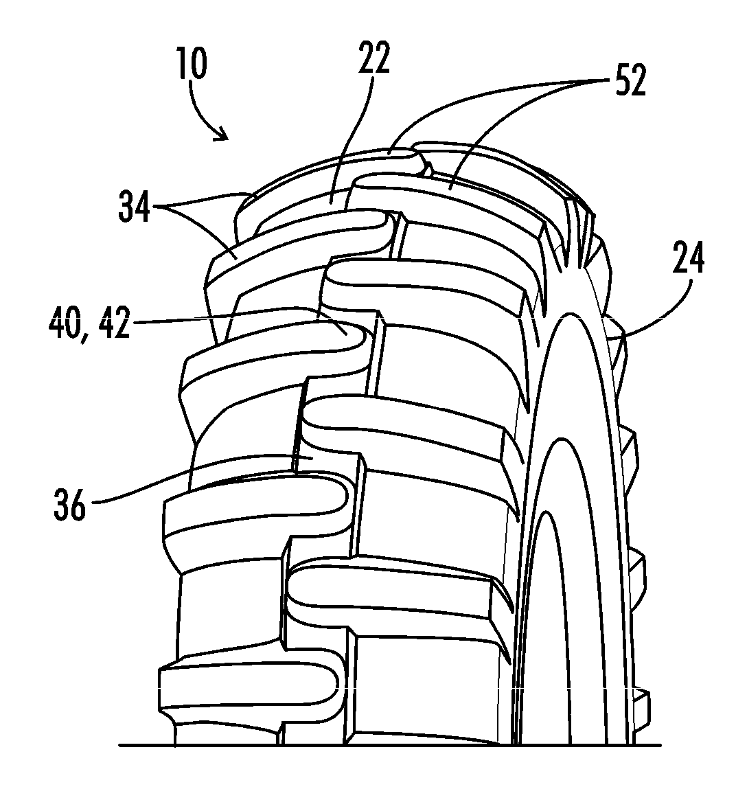
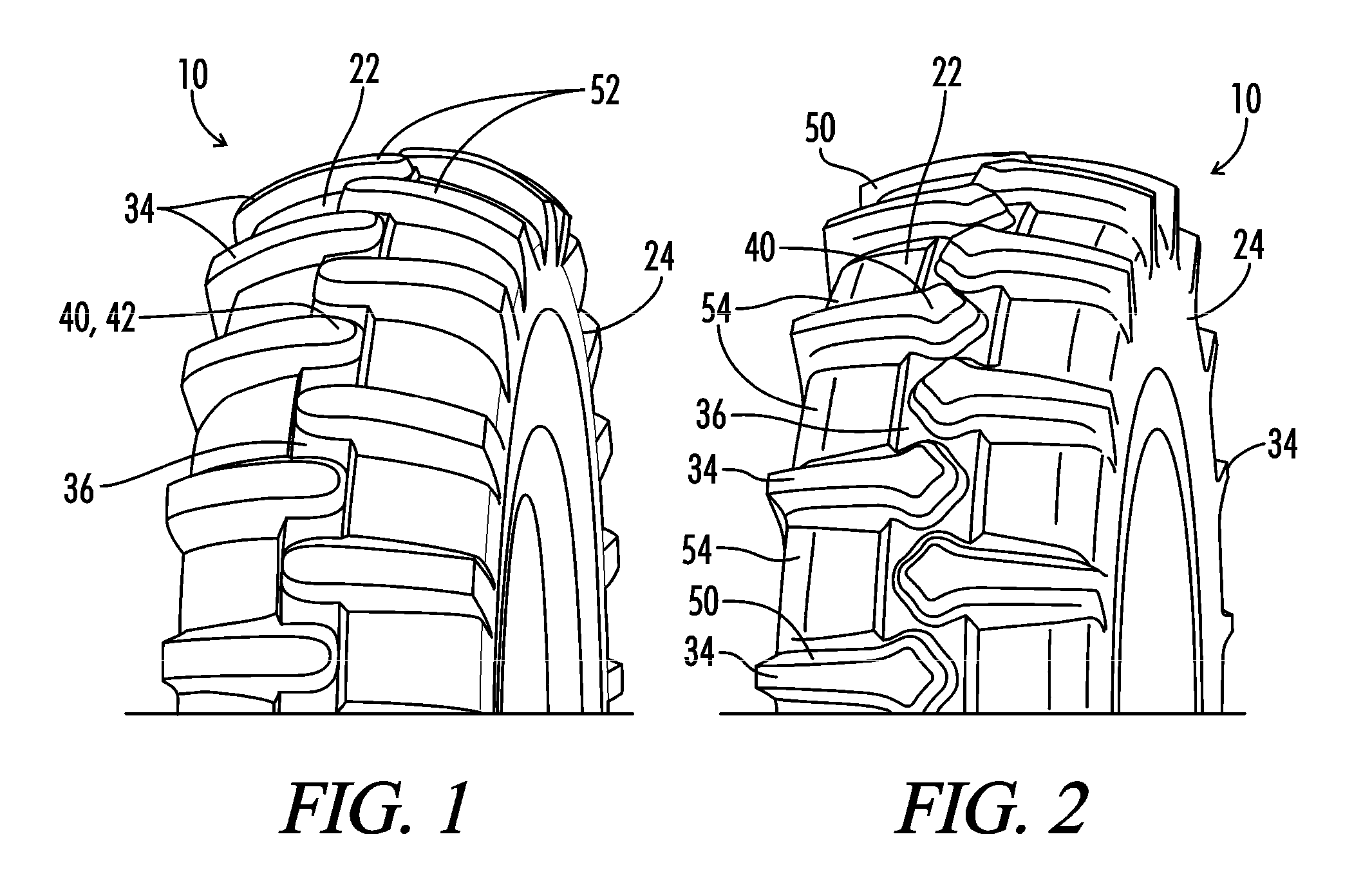
[0037]Referring generally to FIGS. 1-16, a tire is shown and generally designated by the numeral 10. The tire 10 is preferably used to support an agricultural irrigation system 12 as the agricultural irrigation system 12 traverses across a surface 14. The surface 14 is preferably a field in need of hydration. Tire 10 is a non-directional pneumatic tire having a diameter 16 and a width 18 sufficient to support the agricultural irrigation system 12. The tire 10 is used in connection with a wheel 20 to support the agricultural system 12 on the surface 14.

[0038]Preferably the tire 10 includes a top layer or top wall 22 and side walls 24 and 26 that define an internal chamber 28 when the tire 10 is positioned on the wheel 20. The internal chamber 28 can be shaped to hold a gas which can provide the pneumatic properties for the tire 10.

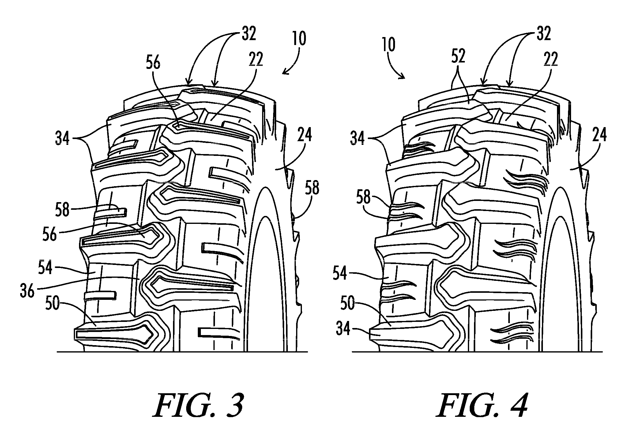
[0039]The tire 10 can include a rotational axis 30 and tread pattern 32 positioned on the tire 10. The tread pattern 32 preferably includes a plurality of ...


PUM


Abstract

A non directional pneumatic tire is provided for an agricultural irrigation system. The tire includes first and second side walls and a radially outer wall defining an internal inflation chamber. A non directional tread pattern is defined on the tire and includes a plurality of longitudinal protrusions positioned substantially parallel to a rotational axis of the tire. The longitudinal protrusions are arranged in first and second rows extending from the first and second side walls toward and across the equatorial plane of the tire. The longitudinal protrusions of the first and second rows circumferentially alternate with each other and there is a circumferential spacing between adjacent longitudinal protrusions at the equatorial plane so that no portion of one longitudinal protrusion circumferentially coincides with or overlaps another.

Description

[0001]We, Bill J. Wallet, a citizen of the United States, residing at Marshallville, Ohio; John J. Regallis, a citizen of the United States, residing at Akron, Ohio; Jeffrey D. Parker, a citizen of the United States, residing at Akron, Ohio; and Nobuo Shimizu, a citizen of Japan, residing at Cuyahoga Falls, Ohio; and Andrew Miklic, a citizen of the United States, residing at Akron, Ohio; have invented a new and useful “Irrigation Tire.”BACKGROUND OF THE INVENTION[0002]1. Field of the Invention[0003]The present invention relates generally to tires and to non-directional tires used in agricultural settings. More specifically, but without limitation, the present invention relates to non-directional pneumatic tires designed to support agricultural irrigation systems.[0004]2. Technical Background[0005]The development of specific tires to fill a specific need for various wheeled devices is well known in the art. Most of this focus has been directed at the development of tires for vehicles...

Claims


Application Information

Patent Timeline
Patent Type & Authority Applications(United States)
IPC IPC(8): B60C11/03
CPCB60C11/0311B60C11/0304B60C11/0316B60C1/00B60C3/04B60C13/00B60C2011/0388B60C11/032B60C11/033B60C11/0332B60C11/1307B60C2200/08
Inventor WALLET, BILL J.REGALLIS, JOHN J.PAKER, JEFFREY D.SHIMIZU, NOBUOMIKLIC, ANDREW T.
Owner BRIDGESTONE AMERICAS TIRE OPERATIONS LLC
Why Eureka
Try Eureka