Open MRI Magnetic Field Generator

a magnetic field generator and open technology, applied in the field of permanent magnet designs, can solve the problems of high cost, limited, and limited use of most whole-body permanent magnet scanners, and achieve the effects of reducing fringe field generation, efficient yoke and return design, and high efficiency and practical design

Active Publication Date: 2009-04-02
LIAN JIANYU +2
View PDF12 Cites 32 Cited by
  • Summary
  • Abstract
  • Description
  • Claims
  • Application Information

AI Technical Summary

Benefits of technology

[0021]In yet another preferred embodiment of this invention there is provided a T-section with the main yoke. In one preferred embodiment this ring section is made of a ferromagnetic material and plays the role of a field clamp significantly reducing fringe field generation. In another embodiment this ring section can be a permanent magnet material magnetized substantially in the axial direction and thereby extend the homogeneous field region in the air gap by up to 5 cm or more. The placement of the T-yoke, pa

Problems solved by technology

However, magnets based on superconducting coil technology require dual cryogen systems and periodic refilling making them expensive to buy and maintain.
Most whole-body permanent magnet based scanners are still below 0.5 Tesla and are limited in certain important applications that require greater field strengths.
The limitations become severe when the required magnetic field is greater than 0.5 Tesla.
Thus, there is a fundamental limit to how much magnetization these materials can produce and the magnets made from them if they are to be compact in size and weight.
Second, the ferromagnetic structures and in particular the poles will saturate rendering the magnet inoperative.
The main source of the problem in conventional magnets is the poles.
However, for typical whole-body systems, as the magnetic field strength in the air gap is required to be greater than about 0.4 T, the poles start to saturate making them ineffective or leading to designs that become impractical because they have to be made very thick.
At f

Method used


Image

  • Open MRI Magnetic Field Generator
  • Open MRI Magnetic Field Generator
  • Open MRI Magnetic Field Generator

Examples


case 10

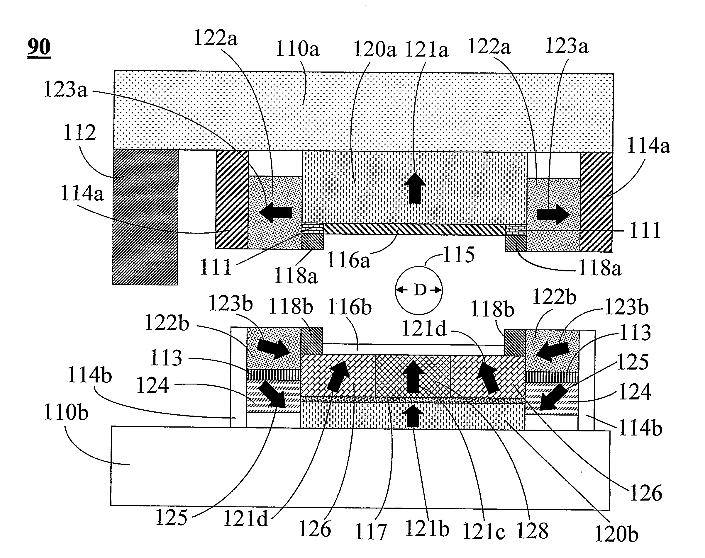
[0085]Case 10 is a check on the effect of just changing the magnetization orientation in the upper portion of the ring magnet 124. The result clearly shows that the central field value is increased by about 30 G without any effect on the homogeneity. Therefore, adjustments of this portion of the ring magnet give fine control over the central field value. Case 11 shows the benefits of changing the edge portion of the L-poles, 111 to a permanent magnet. It adds about 250 G to the central field value and significantly reduces the overall saturation of the L-poles. In contrast changing the Rose shims, 118, to permanent magnets, Case 12, has a similar effect as well and varying the magnetization orientation adjusts saturation of the L-poles and the overall homogeneity.

[0086]In more practical implementations of this magnet system a polygonal shape to the L-magnets and the L-poles is easier in which case the sections have to be at least 8 and preferably 32 or more for a better circumferent...


PUM


Abstract

A magnet primarily for use in MRI applications comprises a pair of poles oriented about a plane of symmetry parallel to each therebetween defining an air gap region, magnetic field sources secured on the surfaces of the poles opposite the air gap that have yokes disposed on them, the yokes connected to each other by returns so that the entire magnet assembly can form a closed magnetic flux circuit to substantially confine the magnetic fields generated by the apparatus in the air gap where an imaging region is formed to place subjects for the purposes of examination. The main assembly being cylindrical in geometry has permanent magnets for magnetic field sources that are composed of two regions, a central disk-like portion magnetized substantially along the axial direction and an outer ring-like region magnetized substantially along the radial direction extending axially to form part of the pole together producing a very efficient and even flux distribution throughout the entire magnet assembly with minimal flux leakage. A further means of reducing flux leakage is incorporated in the yokes which have two sections, a disk-like region and an ring-like section to enclose the permanent magnets. The poles are made of multiple sections with a central disk-like region and an outer ring-like region that is a combination of permanent magnets and high permeability materials. This magnet assembly can achieve 1.0 Tesla or greater magnetic fields for whole-body scanning without saturating the magnet pole and other structures.

Description

PRIORITY CLAIM[0001]This application claims priority from U.S. Provisional Application 60 / 751,450, filed Dec. 19, 2005.BACKGROUND OF THE INVENTION[0002]1. Field of the Invention[0003]The invention relates to a new class of permanent magnet designs that can generate very strong and highly homogeneous fields for NMR, MRI and MRT use. In particular, the magnet is capable of generating field strengths of 1.0 Tesla or greater and still accommodate whole-body imaging without saturating the pole piece and surrounding magnet structures.[0004]2. Description of the Related Art[0005]In MRI the strength of the NMR signal is proportional to the magnetic field and so the greater the magnetic field the stronger the NMR signal which translates into improved image quality and faster acquisition of image data. For whole-body imaging field strengths greater than 0.5 Tesla were only achieved using superconducting coils typically in cylindrical configurations although recently there have been 1.0 Tesla ...

Claims


Application Information

Patent Timeline
IPC IPC(8): H01F7/02
CPCG01R33/383G01R33/3806
Inventor LIAN, JIANYUTEKLEMARIAM, GRUMHU, XIAOPING
Owner LIAN JIANYU
Why Eureka
Try Eureka