Power resistor

a technology of resistor and power supply, applied in the direction of resistor details, resistor adapters for applying terminals, envelope/housing resistor manufacturing, etc., can solve the problem of not being able to address the approach

Inactive Publication Date: 2009-04-02
VISHAY DALE ELECTRONICS INC
View PDF14 Cites 10 Cited by
  • Summary
  • Abstract
  • Description
  • Claims
  • Application Information

AI Technical Summary

Benefits of technology

[0004]According to one aspect of the present invention, a power resistor is provided. The power resistor includes first and second opposite terminations and a resistive element formed from a plurality of resistive element segments between the first and second opposite terminations. There is at least one segmenting conductive strip separating two of the resistive element segments and there is at least one open area between the first and second opposite terminations and separating at least two resistive element segments. The separation of the resistive element segments assists in spreading heat throughout the power resistor. According to another aspect of the present invention, the power resistor or other electronic component may be packaged by bonding the power resistor or other electronic element to a heat sink tab with a thermally conductive and electrically insulative material to thereby mechanically connect the heat sink tab and the electronic element in a heat conducting relation without short circuiting the heat sink tab to the electronic element. The power resistor or other electronic element may be packaged by connecting terminals and forming a molded body to encase the resulting device.
[0005]A method of manufacturing a power resistor includes forming a joined metal strip providing first and second opposite terminations and a resistive element between the first and second opposite terminations wherein the first termination is formed from a first outer metal strip, the resistive element is formed from a middle strip, and the second opposite termination is formed from a second opposite outer metal strip, the three strips joined together to from the joined metal strip. Then the method provides for segmenting the resistive element into a plurality of resistive element segments between the first and second opposite terminations by providing at least one segmenting conductive strip separating two of the resistive element segments and at least one open area between the first and second opposite terminations and separating at least two resistive element segments. The separation of the plurality of resistive element segments assists in spreading heat throughout the power resistor.

Problems solved by technology

Such an approach does not address the metal strip type resistor that does not have an electrically insulative substrate that can go between the resistive element and the metal heat sink tab of the IC package providing electrical isolation of one from the other.
Not having a solution to this problem has denied the electronics industry the benefits of a metal strip resistor's ultra low ohmic values, pulse power handling, low TCR, low thermal EMF, load life stability and low TCR in a high power density IC type package.

Method used


Image

  • Power resistor
  • Power resistor
  • Power resistor

Examples


Embodiment Construction

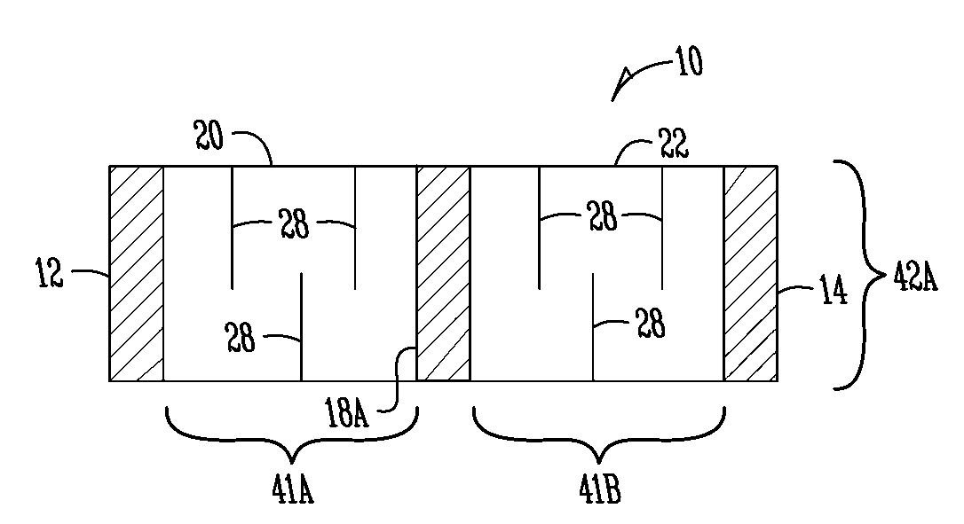
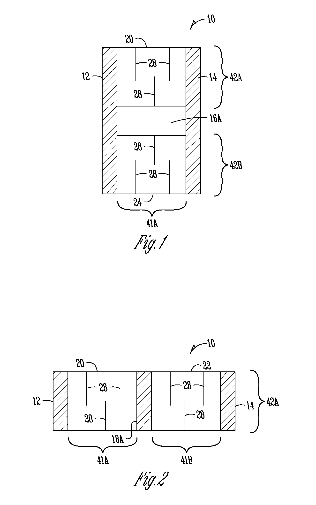
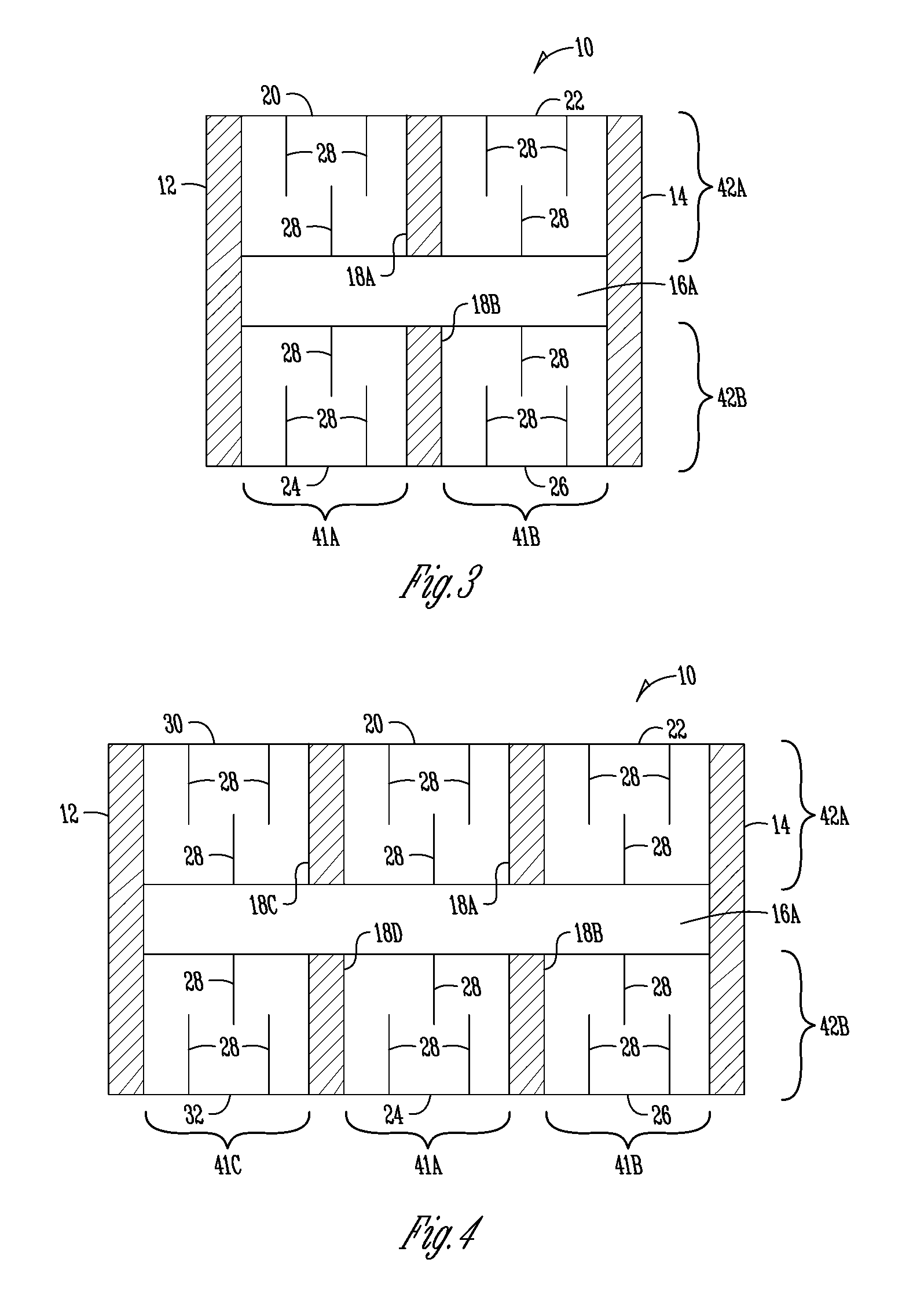
[0028]FIG. 3 illustrates one embodiment of a free standing resistor 10 formed of a metal strip which is segmented. The resistor 10 has a first conductive strip 12 and an opposite second conductive strip 14 to form opposite terminals for the resistor 10. An open area 16A is shown between the first conductive strip 12 and the opposite second conductive strip 14. Segmenting conductive strips 18A, 18B are also shown. The open area 16A and the segmenting conductive strips 18A, 18B serve to segment the resistive element of the resistor 10 into four segments 20, 22, 24, 26. Within each of the four segments 20, 22, 24, 26, slots 28 are cut to adjust resistivity and form a serpentine current path.

[0029]The configuration shown in FIG. 3 provides significant advantages. In particular, the segmentation forces the heat to be spread out over a larger portion of the resistive element thus reducing the peak temperature in any one spot. In particular, compared to an unsegmented resistive element wit...


PUM

PropertyMeasurementUnit
conductiveaaaaaaaaaa
thermally conductiveaaaaaaaaaa
electrically insulativeaaaaaaaaaa

Abstract

A resistor includes first and second opposite terminations, a resistive element formed from a plurality of resistive element segments between the first and second opposite terminations, at least one segmenting conductive strip separating two of the resistive element segments, and at least one open area between the first and second opposite terminations and separating at least two resistive element segments. Separation of the plurality of resistive element segments assists in spreading heat throughout the resistor. The resistor or other electronic component may be packaged by bonding to a heat sink tab with a thermally conductive and electrically insulative material. The resistive element may be a metal strip, a foil, or film material.

Description

BACKGROUND OF THE INVENTION[0001]The present invention relates generally to a power resistor with a free standing element. A free standing resistor has a resistor element formed of a material having sufficient thickness to be self supporting without the aid of a substrate. More particularly, but not exclusively, the present invention relates to maximizing the wattage rating of a power resistor. In addition, the present invention relates to spreading heat across the resistive element of a resistor to thereby improve performance.[0002]In addition, the present invention relates to maximizing the wattage rating of a power resistor while minimizing the physical dimensions of the resistor. This challenge has been addressed for film resistor technologies where the resistive element is on a ceramic substrate that can be bonded to the metal tab of a power IC package without electrically shorting the resistive element to the metal tab. Such an approach does not address the metal strip type re...

Claims


Application Information

Patent Timeline
Patent Type & Authority Applications(United States)
IPC IPC(8): H01C1/034H01C17/02H01C17/28H01C7/00
CPCH01C1/014H01C1/08H01C13/02Y10T29/49098Y10T29/49087Y10T29/49101H01C17/23
Inventor ZANDMAN, FELIXSMITH, CLARK L.WYATT, TODD L.VEIK, THOMAS L.BERTSCH, THOMAS L.
Owner VISHAY DALE ELECTRONICS INC
Why Eureka
Try Eureka