

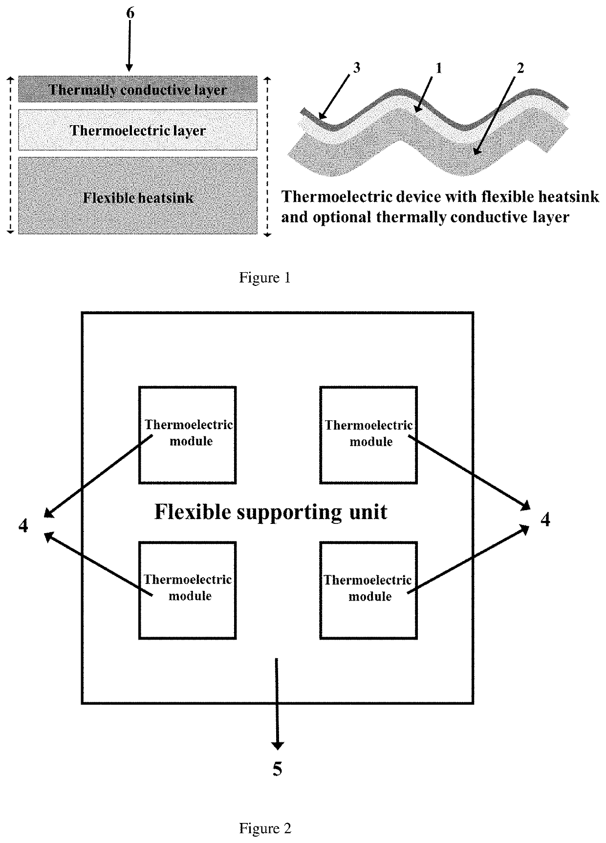
Thermoelectric Device with Flexible Heatsink
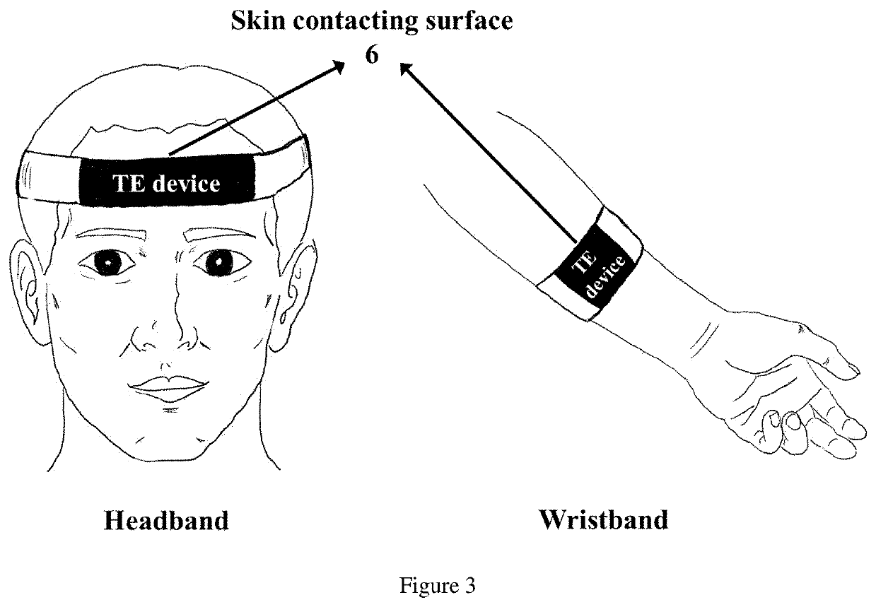
a thermoelectric device and flexible technology, applied in the direction of sports equipment, semiconductor/solid-state device details, wristbands, etc., can solve the problems of inability to adapt to wearable or flexible use, inability to adapt to flexible/wearable applications, brittleness, etc., to achieve the effect of improving the efficiency and working time of te devices
- Summary
- Abstract
- Description
- Claims
- Application Information
AI Technical Summary
Benefits of technology
Problems solved by technology
Method used
Image

Examples
example 1
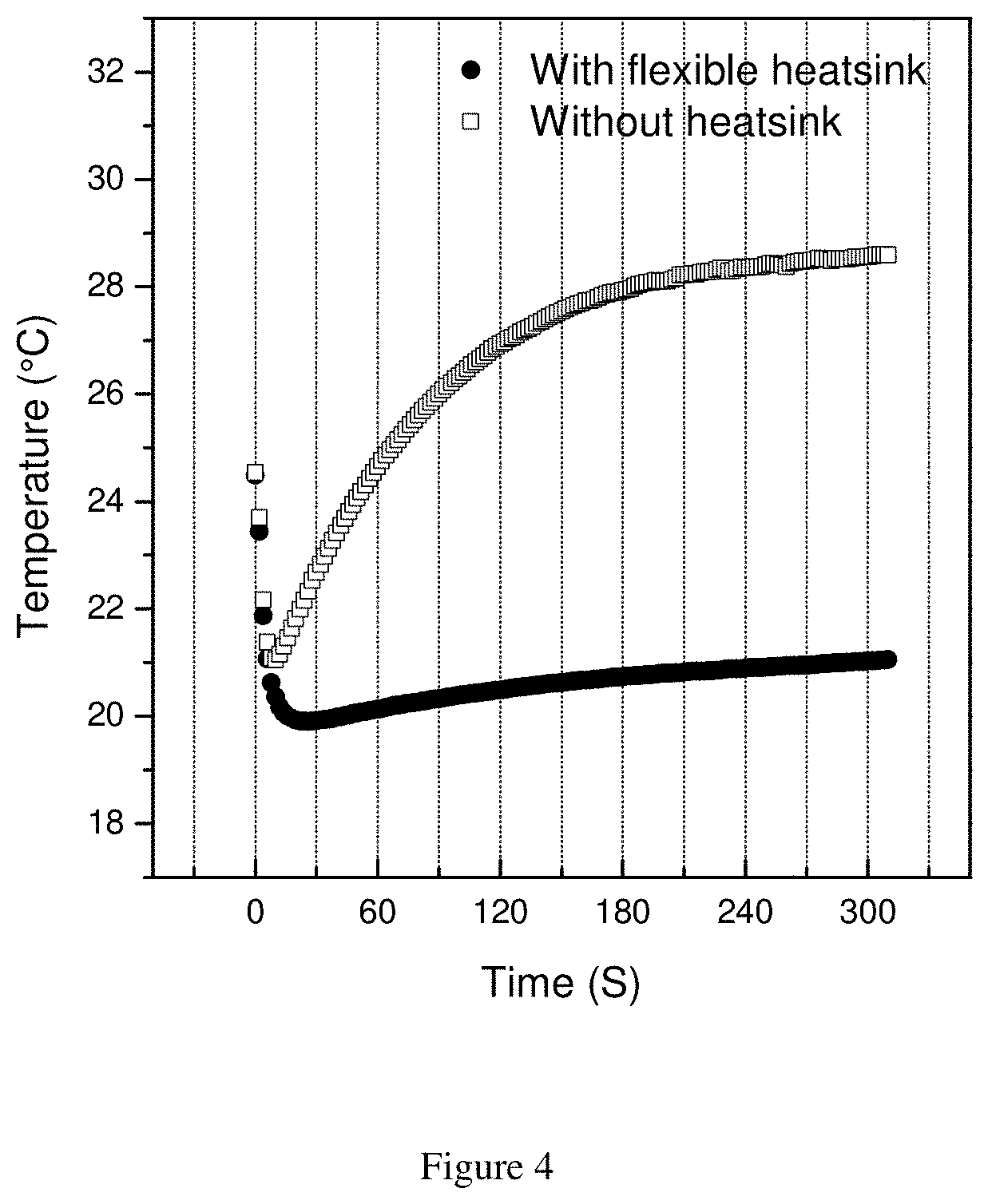
[0035]A prototype flexible TE device was prepared by combining a TE layer and a heatsink layer. To make the TE layer, a commercial TE (Peltier) module (15 mm×15 mm×5 mm) was embedded in Ecoflex® silicone rubber. The heatsink layer was made by blending Ecoflex® silicone rubber (55 wt %), graphite powder (30 wt %), and EnFinit® PCM 28 CPS powder (15 wt %). 0.75 Voltage was applied to the TE device and the temperature of the cold surface of the device was measured with time. For comparison, the temperature of the same TE layer without the heatsink was measured.
[0036]FIG. 4 shows the short-term cooling performance of the TE layer with and without the heatsink. Without the heatsink, the TE layer could not keep cooling more than 60 seconds, whereas the TE layer with heatsink kept cooling below the initial temperature by around 4° C. for over 300 seconds.
[0037]FIG. 5 shows the long-term cooling performance of the TE layer with the heatsink. It is shown that around 3° C. cooling was kept du...
PUM
 Abstract
Description
Claims
Application Information