Circuit device, circuit module, and outdoor unit

a circuit module and circuit technology, applied in the direction of power cables, cables, insulated conductors, etc., can solve the problems of difficult to solve, increase in electricity consumption, emission of carbon dioxide gas into the atmosphere, etc., and achieve the effect of suppressing thermal interference between circuit elements and increasing packaging density

Inactive Publication Date: 2009-04-02
SEMICON COMPONENTS IND LLC
View PDF28 Cites 59 Cited by
  • Summary
  • Abstract
  • Description
  • Claims
  • Application Information

AI Technical Summary

Benefits of technology

[0018]The present invention has been made in view of the problems described above. A main object of the present invention is thus to provide a circuit device, a circuit module, and an outdoor unit capable of increasing the packaging density and suppressing the thermal interference between circuit elements to be incorporated therein.

Problems solved by technology

One of various causes for the warming is an increase in electricity consumption.
The generation of electricity depends largely on the exhausting oil, and the burning of the oil causes the problem of the emission of the carbon dioxide gas into the atmosphere.
Another cause of the warming is automobiles, most of which use gasoline for fuel.
The electricity serves as the power source for the electronic equipments such as a washing machine, an air conditioner, and a mobile device, and is indispensable for human beings living on the earth to maintain a cultural life, and thus the increase in electricity consumption is an issue difficult to solve.
Unlike in the old days, driving the automobile while using various functions in the vehicle interior results in an increase in energy consumption eventually.
As a result, the microcomputer heated by the power transistor might cause a misoperation.
Accordingly, this condition causes a crack or the like in the electrically connected portion of the circuit module, and therefore, a countermeasure for releasing, to the outside, the heat generated in the circuit module is required.

Method used


Image

  • Circuit device, circuit module, and outdoor unit
  • Circuit device, circuit module, and outdoor unit
  • Circuit device, circuit module, and outdoor unit

Examples


first embodiment

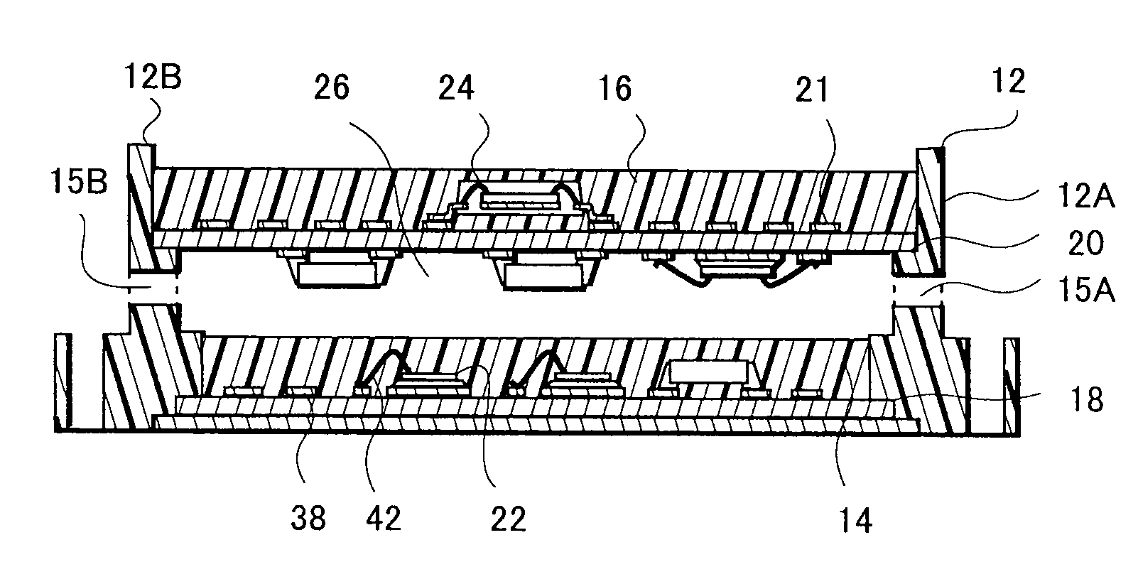
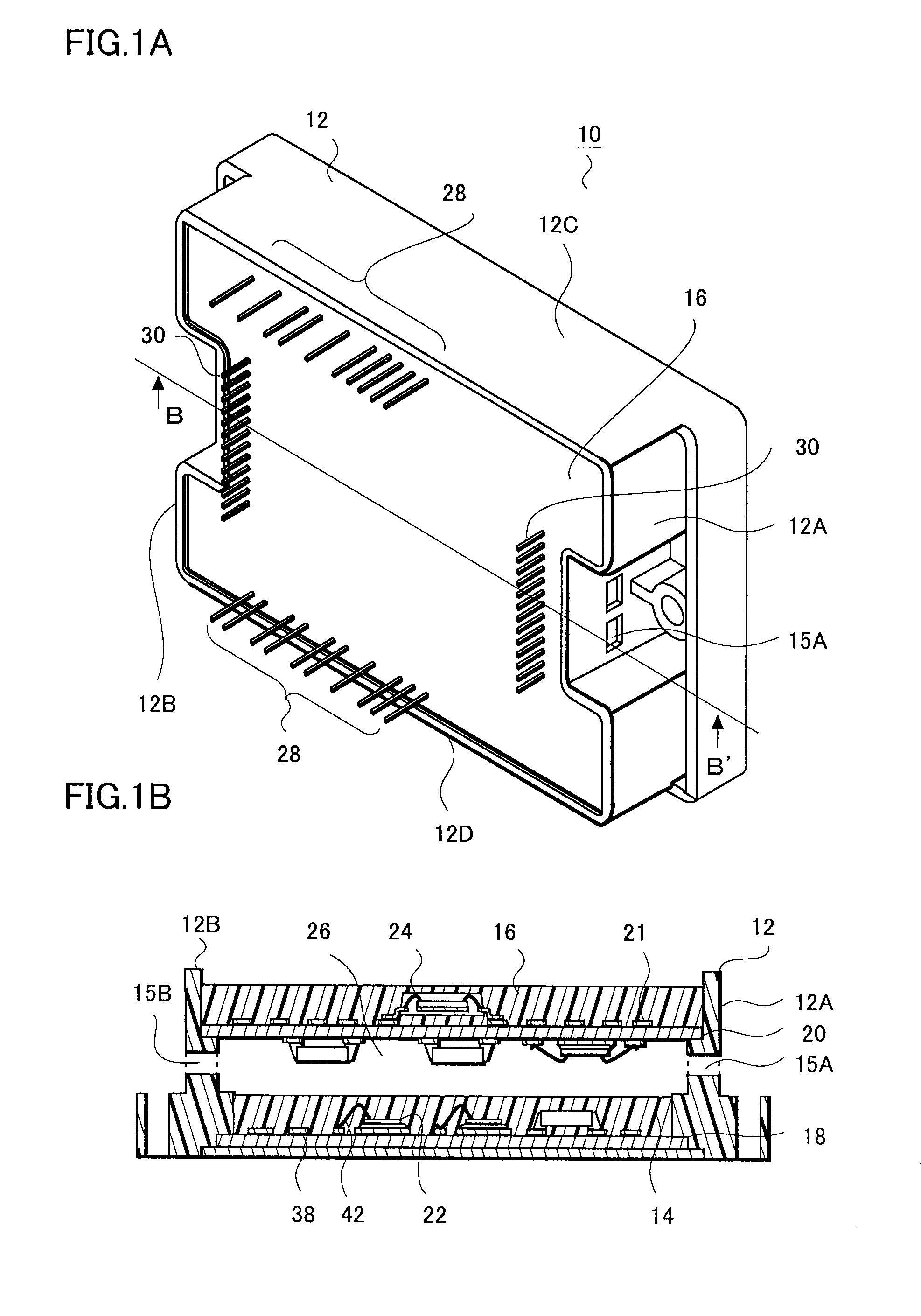
[0038]As an example of the circuit device, the configuration of a hybrid integrated circuit device 10 is described with reference to FIGS. 1A and 1B. FIG. 1A is a perspective view of the hybrid integrated circuit device 10, and FIG. 1B is a cross sectional view of FIG. 1A taken along a B-B′ line.

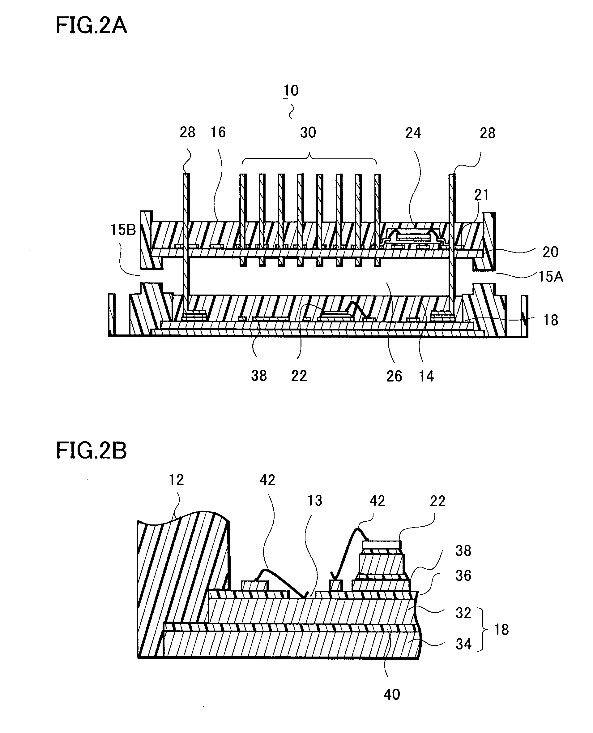
[0039]As shown in FIG. 1A and FIG. 1B, in the hybrid integrated circuit device 10, a first circuit board 18 is overlaid with a second circuit board 20 and both circuit boards are incorporated into a case member 12. A first circuit element 22 (a power transistor, for example) is arranged on the upper face of the first circuit board 18, and a second circuit element (a microcomputer, for example) is arranged on the upper face of the second circuit board 20. In addition, inside the case member 12, a hollow portion 26 (internal space) which is not filled with a sealing resin is provided, and this hollow portion 26 and the outside communicate with each other through communicating openings 15A, 15B...

second embodiment

[0089]A second embodiment is described with reference to FIG. 6A, FIG. 6B and FIG. 7. The contents of this embodiment are basically the same as those of the first embodiment, and the difference therebetween lies in the configuration of the opening 19 for allowing the inside of the device to communicate with the outside.

[0090]The configuration of the hybrid integrated circuit device 10 according to this embodiment of the present invention is described with reference to FIG. 6A and FIG. 6B. FIG. 6A is a perspective view showing the hybrid integrated circuit device 10, and FIG. 6B is a cross sectional view of the hybrid integrated circuit device 10 taken along a B-B′ line of FIG. 6A.

[0091]As shown in FIG. 6A, four openings 19 for allowing the hollow portion 26 of the case member 12 to communicate with the outside are provided at the corners of the case member 12. Each of the opening 19 exhibits a square shape in plan view, and is formed by causing the side wall of the case member 12 to...

third embodiment

[0102]The configuration of a circuit module of this embodiment is described with reference to FIGS. 8A, 8B, 9, 10, 11, 12 and 13.

[0103]As shown in FIG. 8A, two metal substrates are employed in this embodiment. A lower metal substrate 201B is a base substrate, and is formed larger than the above first substrate 201A by L2 on each of the four sides of 201A. The distance L2, referred to as extending distance, improves the voltage resistance characteristic of the first substrate 201A and the rear surface of the base substrate 201B when the actual circuit module is formed.

[0104]First, a case member 203 is described. The case member 203 is in the form such as a square pole with an interior area removed. In other words, the case member 203 is formed integrally with four side walls, i.e., 203A on a front side of the figure, 203B on a far side thereof, 203C on the left side thereof and 203D on the right side thereof. Accordingly, there are openings 220, 221 respectively on the lower side and...


PUM


Abstract

Provided is a circuit device capable of increasing the packaging density and also suppressing the thermal interference between incorporated circuit elements. In a hybrid integrated circuit device, a first circuit board and a second circuit board are incorporated into a case member being arranged in a way that the first circuit board is overlaid with the second circuit board. A first circuit element is arranged on the upper face of the first circuit board and a second circuit element is arranged on the upper face of the second circuit board. In addition, inside the case member, a hollow portion (internal space) which is not filled with a sealing resin is provided, and this hollow portion communicates with the outside through a communicating opening, which is provided by partially opening the case member.

Description

[0001]This application claims priority from Japanese Patent Application Number JP 2007-252202, filed on Sep. 27, 2007, JP 2007-250484 filed on Sep. 27, 2007, and JP 2007-284349 filed on Oct. 31, 2007, the content of which is incorporated herein by reference in its entirety.BACKGROUND OF THE INVENTION[0002]1. Field of the Invention[0003]The present invention relates to a circuit device, a circuit module, and an outdoor unit, and in particular, relates to a circuit device, a circuit module, and an outdoor unit in which a hybrid integrated circuit formed on an upper face of a circuit board is sealed with a case member.[0004]2. Description of the Related Art[0005]In recent years, newspapers report environmental destruction, signs of global warming, and the causes of the warming. One of various causes for the warming is an increase in electricity consumption. The generation of electricity depends largely on the exhausting oil, and the burning of the oil causes the problem of the emission...

Claims


Application Information

Patent Timeline
Patent Type & Authority Applications(United States)
IPC IPC(8): H05K7/00H05K7/20
CPCH05K1/144H05K7/20009H01L2224/48091H01L2924/13055H01L2924/19105H01L2224/73265H01L2924/1305H01L2924/00014H01L2924/00
Inventor SAKAMOTO, HIDEYUKISAITO, HIDEFUMIKOIKE, YASUHIROTSUKIZAWA, MASAO
Owner SEMICON COMPONENTS IND LLC
Why Eureka
Try Eureka