Time-multiplexed optical waveform generation

a technology of time-multiplexed optical waveforms and optical waveforms, applied in time-division optical multiplex systems, multi-component communication, electromagnetic transmission, etc., can solve the problem that the phase modulator cannot be driven to an arbitrary phas

Inactive Publication Date: 2009-04-02
MASSACHUSETTS INST OF TECH
View PDF14 Cites 28 Cited by
  • Summary
  • Abstract
  • Description
  • Claims
  • Application Information

AI Technical Summary

Benefits of technology

[0003]According to one aspect of the invention, there is provided a time-multiplexed waveform generator. The time-multiplexed waveform generator includes a wavelength splitter that receives an input optical signal and spectrally separates the input optical signal into a plurality of frequency components. A plurality of intensity modulators receives each of the frequency components and passes each of the frequency components for a selective time period, and then extinguishes that frequency for the remainder of a chirp time, the plurality of intensity modulators producing a plurality of first output signals. A plurality of adjustable delay lines is positioned after the intensity modulators and receives the first output signals. Each of the adjustable delay lines enables phase control of each of the frequency components associated with the first output signals for compensating any relative drifts of the path lengths and phase coherently stitching a plurality of sub-chirps together. The adjustable delay lines produce a plurality of second output signals. A wavelength combiner receives the second output signals and recombines the output signals to produce a stair-step waveform output signal.
[0004]According to another aspect of the invention, there is provided a method of performing time-multiplexed waveform generation. The method includes receiving an input optical signal and spectrally separating the input optical signal into a plurality of frequency components. Also, the method includes passing each of the frequency components for a selective time period, and then extinguishing that frequency for the remainder of a chirp time, a plurality of first output signals being produced. Moreover, the method includes enabling phase control of each of the frequency components associated with the first output signals for compensating any relative drifts of the path lengths and phase coherently stitching a plurality of sub-chirps together, a plurality of second output signals being produced. Furthermore, the method includes recombining the second output signals to produce a stair-step waveform output signal.

Problems solved by technology

However, a phase modulator cannot be driven to an arbitrary phase, and so implementations of this strategy have required multiple waveform generators interleaved together to simulate a continuous linear phase ramp.

Method used


Image

  • Time-multiplexed optical waveform generation
  • Time-multiplexed optical waveform generation
  • Time-multiplexed optical waveform generation

Examples


Embodiment Construction

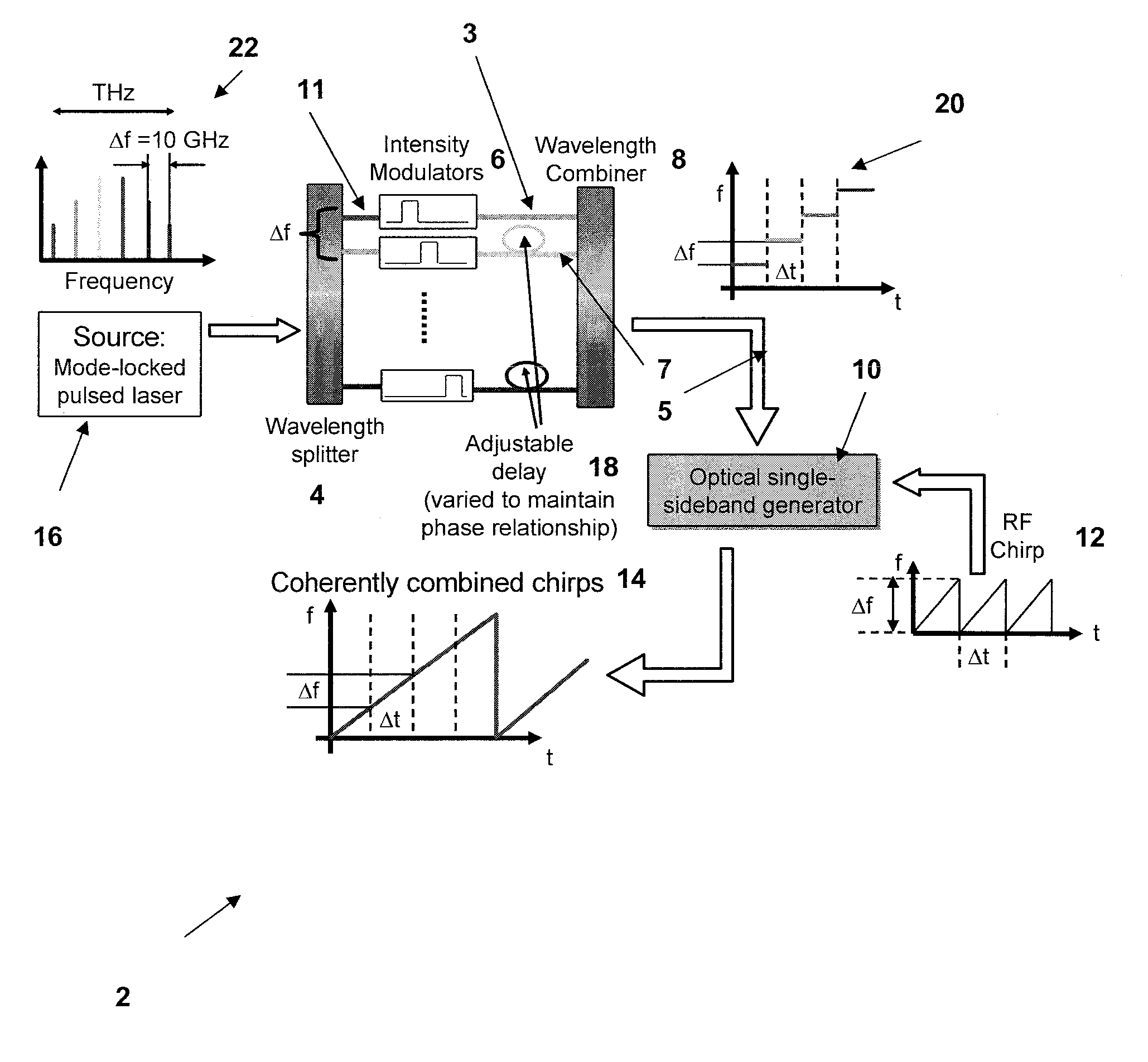
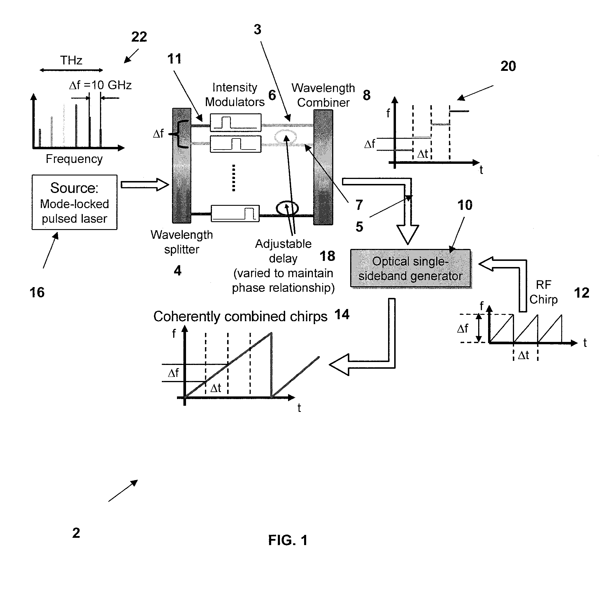
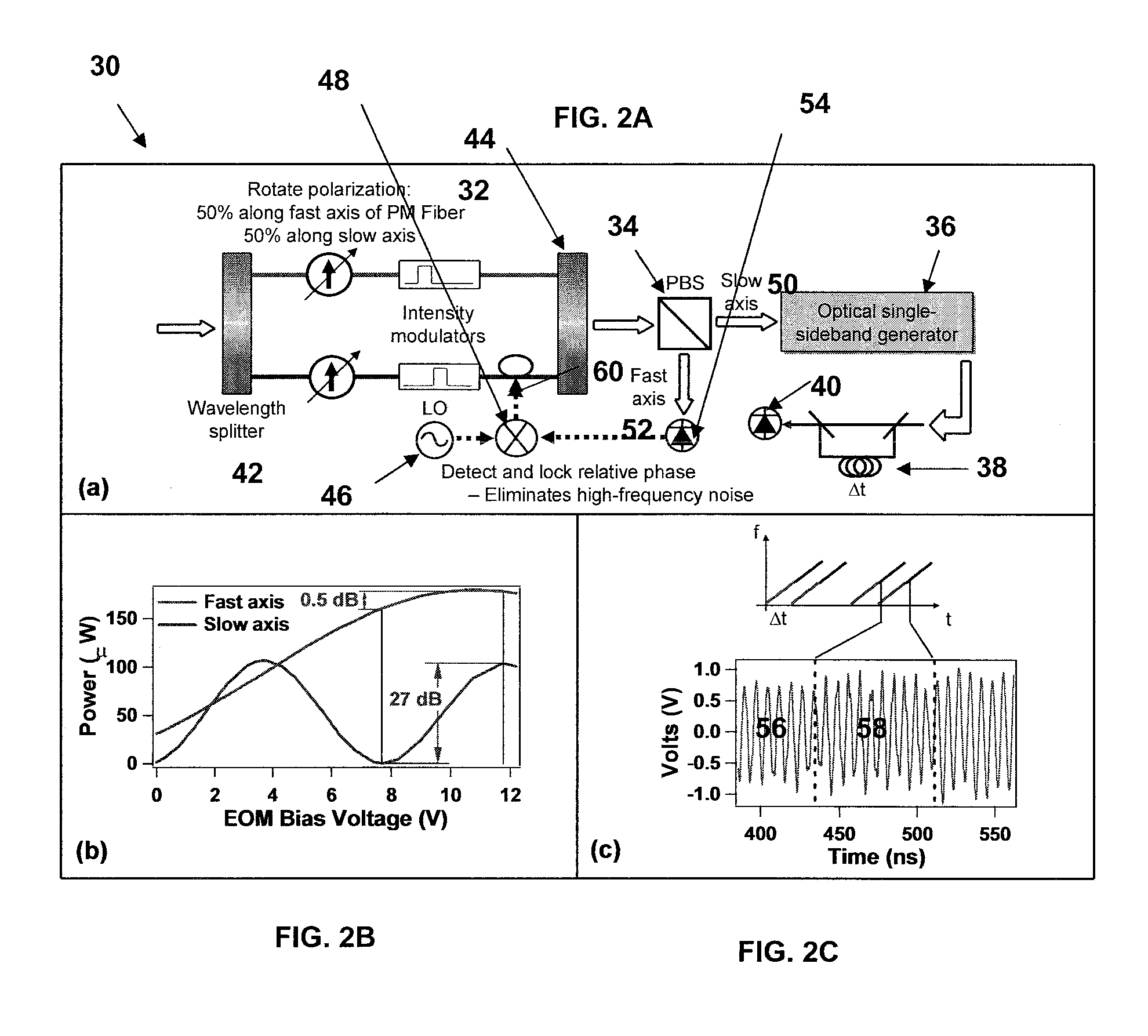
[0007]The invention involves a novel technique for manipulating the pulse train from a mode-locked laser to generate a custom optical waveform. Specifically, the invention is a technique to produce a broadband linear optical frequency ramp that covers 1.5 THz chirp in 75 μs.

[0008]The invention uses the discrete frequency lines of the frequency comb produced by a mode-locked laser 16 to generate many sub-chirps that are sequentially combined phase-coherently to construct a single broadband linear frequency ramp, as shown in FIG. 1. The comb components 11 are first spectrally separated by wavelength splitter 4 so each is transmitted along a separate optical path. Each frequency then passes through an electro-optic intensity modulator 6, which passes each frequency for 0.5 μs, and then extinguishes that frequency for the remainder of the chirp time in an output signal 3. The timing of the modulators 6 is adjusted so that recombination of the frequencies produces a stair-step waveform o...


PUM


Abstract

A time-multiplexed waveform generator includes a wavelength splitter that receives an input optical signal and spectrally separates the input optical signal into a plurality of frequency components. A plurality of intensity modulators receives each of the frequency components and passes each of the frequency components for a selective time period, and then extinguishes that frequency for the remainder of a chirp time, the plurality of intensity modulators producing a plurality of first output signals. A plurality of adjustable delay lines is positioned after the intensity modulators and receives the first output signals. Each of the adjustable delay lines enables phase control of each of the frequency components associated with the first output signals for compensating any relative drifts of the path lengths and phase coherently stitching a plurality of sub-chirps together. The adjustable delay lines produce a plurality of second output signals. A wavelength combiner receives the second output signals and recombines the output signals to produce a stair-step waveform output signal.

Description

BACKGROUND OF THE INVENTION[0001]The invention relates to the field of generating custom-designed optical waveforms, and in particular to manipulating the pulse train from a mode-locked laser to generate a custom optical waveform.[0002]Previous implementations of broadband frequency chirps for high-resolution laser radar (lidar) have involved sweeping tunable CW laser sources, resulting in relatively slow chirps (1.5 THz in hundreds of ms) that have nonlinear contributions that must be measured and compensated. There has been recent interest in using the frequency components of a mode-locked laser to generate arbitrary optical waveforms. All of the previous works in this field have utilized architectures requiring high-speed control of the amplitude and phase of each component using the Fourier transform relationship to generate the waveform of interest. The only way to shift the frequency of one component is to apply a linear phase ramp on one of the phase modulators, referred to a...

Claims


Application Information

Patent Timeline
Patent Type & Authority Applications(United States)
IPC IPC(8): H04J14/08
CPCH04B10/508H01S3/0057
Inventor HOLMAN, KEVIN W.KOCHER, DAVID G.KYUNG, JAE H.JIANG, LEAF A.KAUSHIK, SUMANTHHEINRICHS, RICHARD M.
Owner MASSACHUSETTS INST OF TECH
Why Eureka
Try Eureka