Sliding Vane Compression and Expansion Device

Inactive Publication Date: 2009-04-02
WHITESELL ROBERT
View PDF36 Cites 22 Cited by
  • Summary
  • Abstract
  • Description
  • Claims
  • Application Information

AI Technical Summary

Benefits of technology

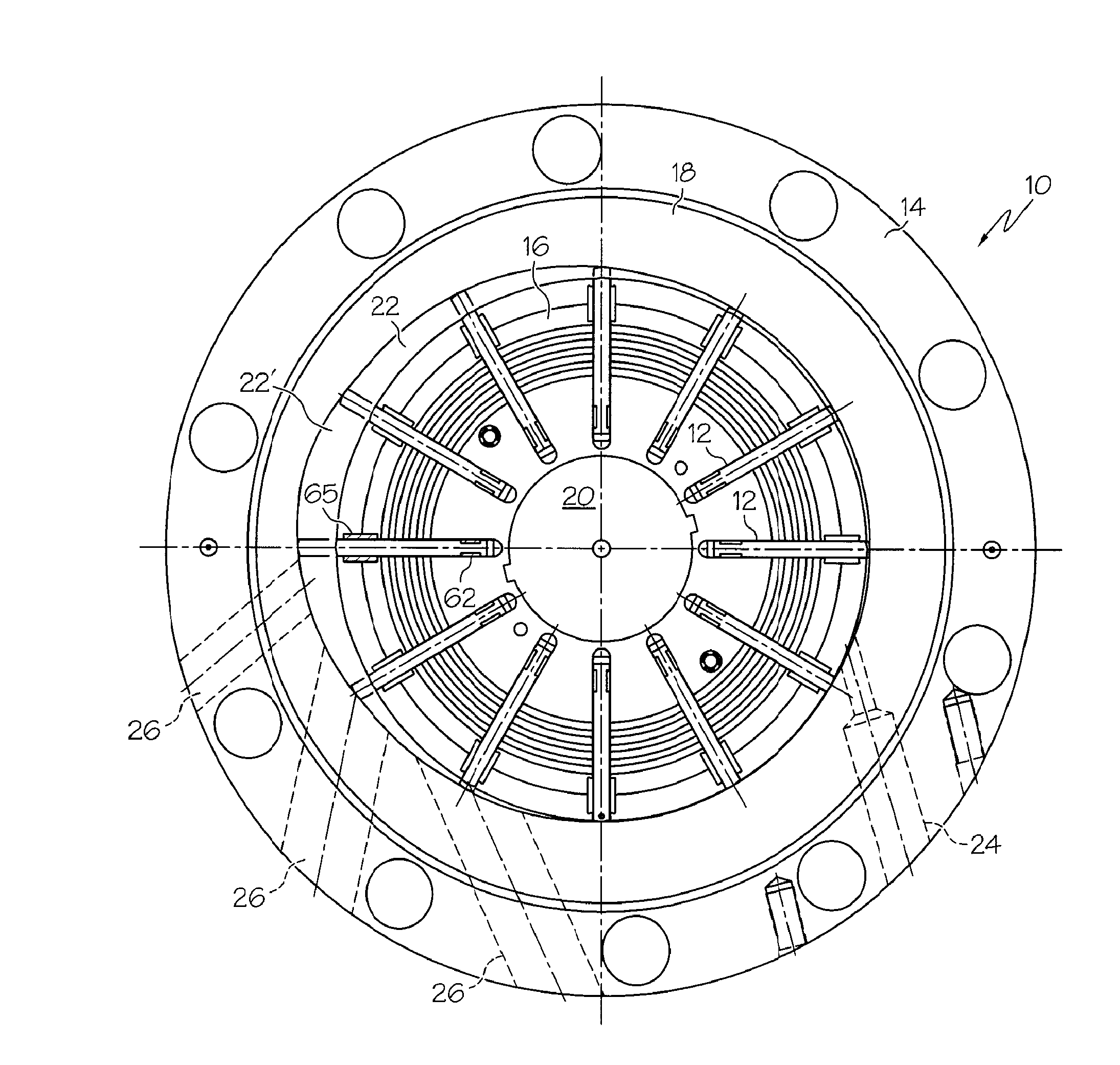
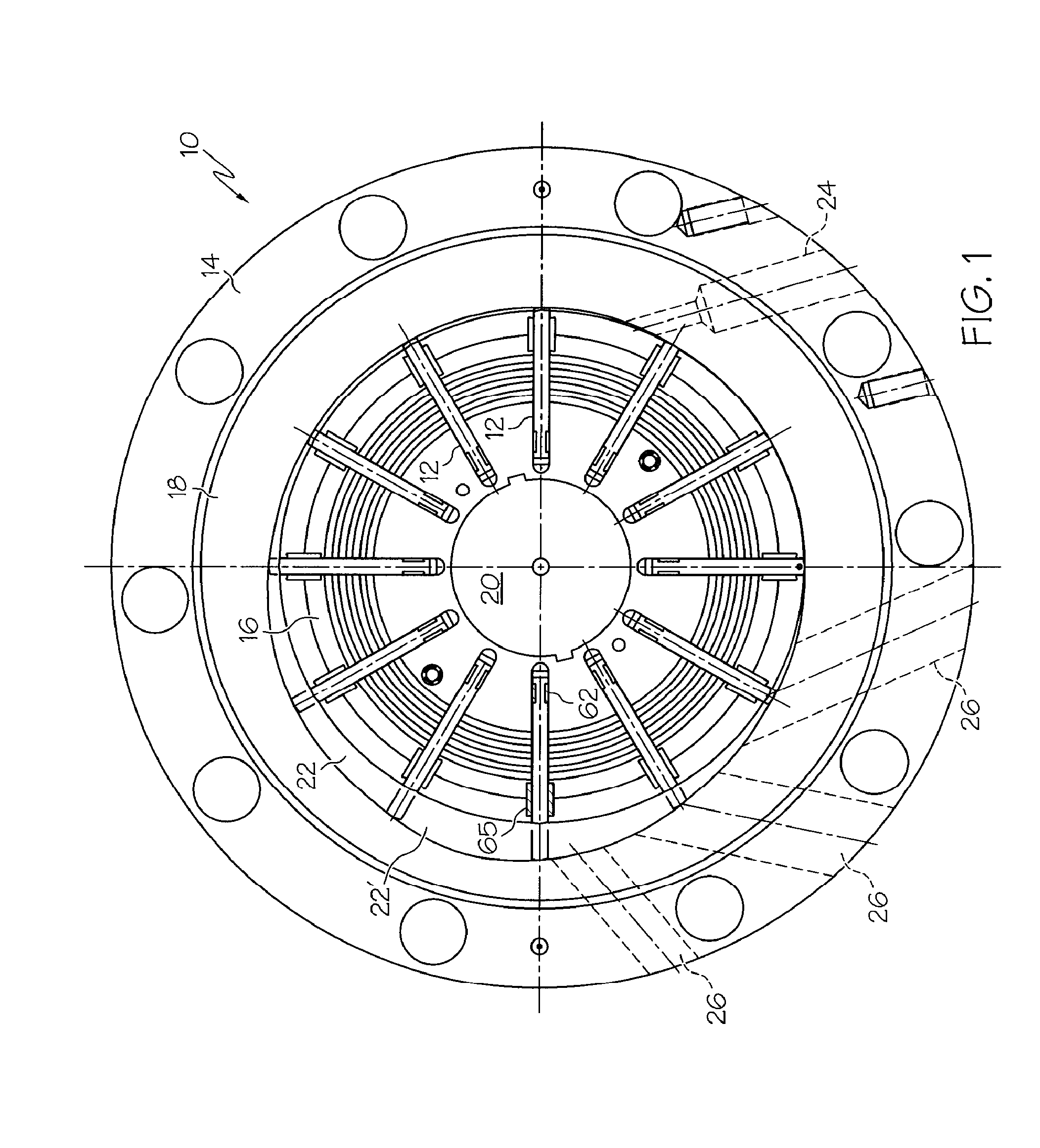
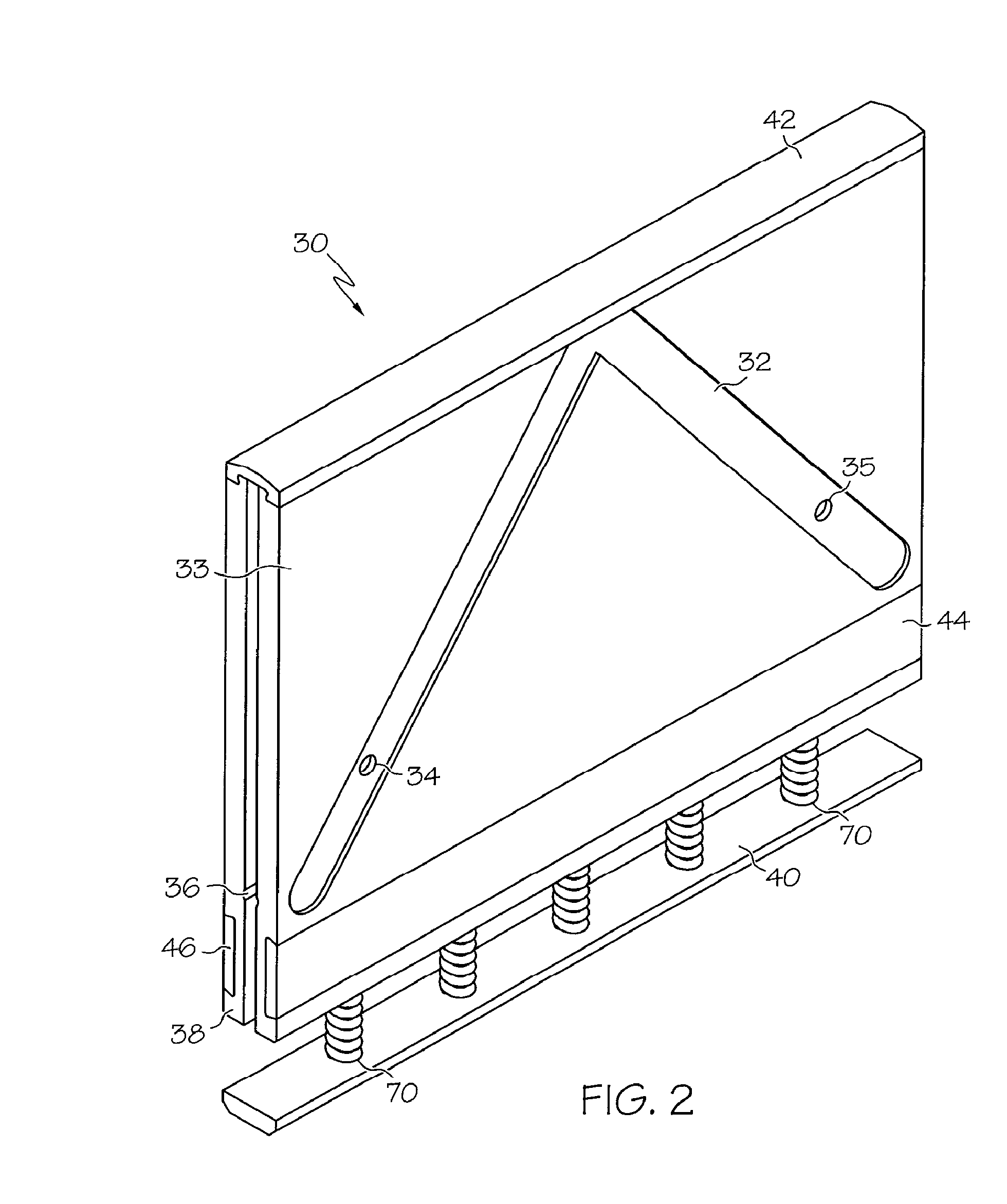
[0010]Another aspect of the invention provides a sliding vane expander/compressor device for receiving a cooled, compressed natural gas feed stream and expanding the stream to form a bi-phase stream with a vapor component and a liquid component, the device comprising: (a) a stator comprising an inner polydynamic ellipse profile, an inlet port and at least one discharge port; (b) a rotor rotatably supported in the stator for rotation about a main shaft, the rotor comprising a plurality of vane slots for receiving sliding vanes; and (c) a plurality of sliding vanes, each vane adapted to be slidably mounted within one of the plurality of vane slots in the rotor, wherein each sliding vane comprises: (i) a vane vent operable to provide an escape path for fluid; (ii) a vane tip insert configured to be retained at the top of the vane, wherein the vane tip insert is made of a low friction material; (iii) a pair of vane bearing inserts configured to be retained within each bottom face of the vane; (iv) a pair of vane side seal inserts operable to seal the side ends of the vane against the rotor housing, wherein each of the vane side seal inserts are preloaded from behind by a waffle spring; and (v) a plurality of vane load springs adapted to stabilize the vane tip within the stator.
[0011]Another aspect of the invention provides a positive displacement sliding vane expander/compressor device, c

Problems solved by technology

Materials of construction are normally limited to very basic materials and uses to very benign types of fluid media.
Although the functionality of such means of vane actuation have been proven, they are characterized in some respects with increase

Method used


Image

  • Sliding Vane Compression and Expansion Device
  • Sliding Vane Compression and Expansion Device
  • Sliding Vane Compression and Expansion Device

Examples


Embodiment Construction

[0021]As used herein, the term “ambient temperature” refers to the temperature of the air surrounding an object. Typically the outdoor ambient temperature is generally between about 0 to 110 degrees Fahrenheit (° F.) (−18 to 43 degrees Celsius (° C.)).

[0022]The term “cryogenic gas” refers to a substance which is normally a gas at ambient temperature that can be converted to a liquid by pressure and / or cooling. A cryogenic gas typically has a boiling point of equal to or less than about −130° F. (−90° C.) at atmospheric pressure.

[0023]The term “hydraulic lock” refers to a condition where a vane would be prevented from receding into its rotor groove, thus preventing rotor rotation and perhaps causing structural damage to the machine.

[0024]The terms “liquefied natural gas” or “LNG” refers to natural gas that is reduced to a liquefied state at or near atmospheric pressure.

[0025]The term “natural gas” refers to raw natural gas or treated natural gas. Raw natural gas is primarily comprise...


PUM


Abstract

A sliding vane compression and expansion device for both cryogenic and normal refrigeration cycles, including the production of liquefied natural gas, is disclosed herein. The device can operate in extreme conditions of pressure and temperature, and incorporates replaceable wear elements as well as functional design elements into a sliding vane device to permit processing of a wide variety of gases (for example, but not limited to, methane, nitrogen, oxygen, argon, etc.), liquids and other media under very extreme conditions, including, but not limited to, super-heated steam, cryogenic liquids, bi-phase gas/liquids (wherein both gaseous and liquid media co-exist or are created in the same area), plasma media, semi-solids and powders.

Description

CROSS REFERENCE TO RELATED APPLICATION[0001]This application claims the benefit of U.S. Provisional Application No. 60 / 976,048, filed Sep. 28, 2007.FIELD OF THE INVENTION[0002]The present invention relates in general to cryogenic refrigeration cycles useful in commercial and industrial applications including the liquefaction of gases, and more particularly to a sliding vane compression / expansion device that can operate in extreme conditions of pressure and temperature differentials and incorporate a very high expansion / compression ratio to deliver high operating efficiencies.BACKGROUND OF THE INVENTION[0003]Typical sliding vane expanders / compressors are designed as low cost, medium efficiency pieces of equipment. Materials of construction are normally limited to very basic materials and uses to very benign types of fluid media. There are of course some exceptions in special applications. Most common uses are for low-pressure air motors / compressors and low-pressure liquid (hydraulic)...

Claims


Application Information

Patent Timeline
IPC IPC(8): F04C27/00F04C29/12F04C18/344F04C29/00
CPCF01C21/0845F04C2/3442F04C2220/22F04C2210/24F04C13/001
Inventor WHITESELL, ROBERT
Owner WHITESELL ROBERT
Why Eureka
Try Eureka