Tagged particles for downhole application

a technology of tagged particles and downhole applications, applied in the field of subsurface tagging and monitoring techniques, can solve the problems that radioactive substances as tracers are not always desirable, and achieve the effect of improving the accuracy of tagging

Inactive Publication Date: 2009-04-02
SCHLUMBERGER TECH CORP
View PDF44 Cites 157 Cited by
  • Summary
  • Abstract
  • Description
  • Claims
  • Application Information

AI Technical Summary

Problems solved by technology

The use of radioactive substances as tracers is not alway...

Method used


Image

  • Tagged particles for downhole application
  • Tagged particles for downhole application
  • Tagged particles for downhole application

Examples


Embodiment Construction

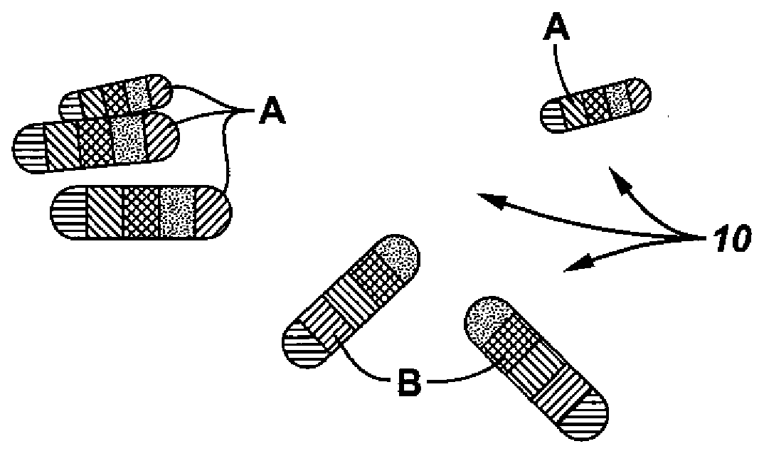
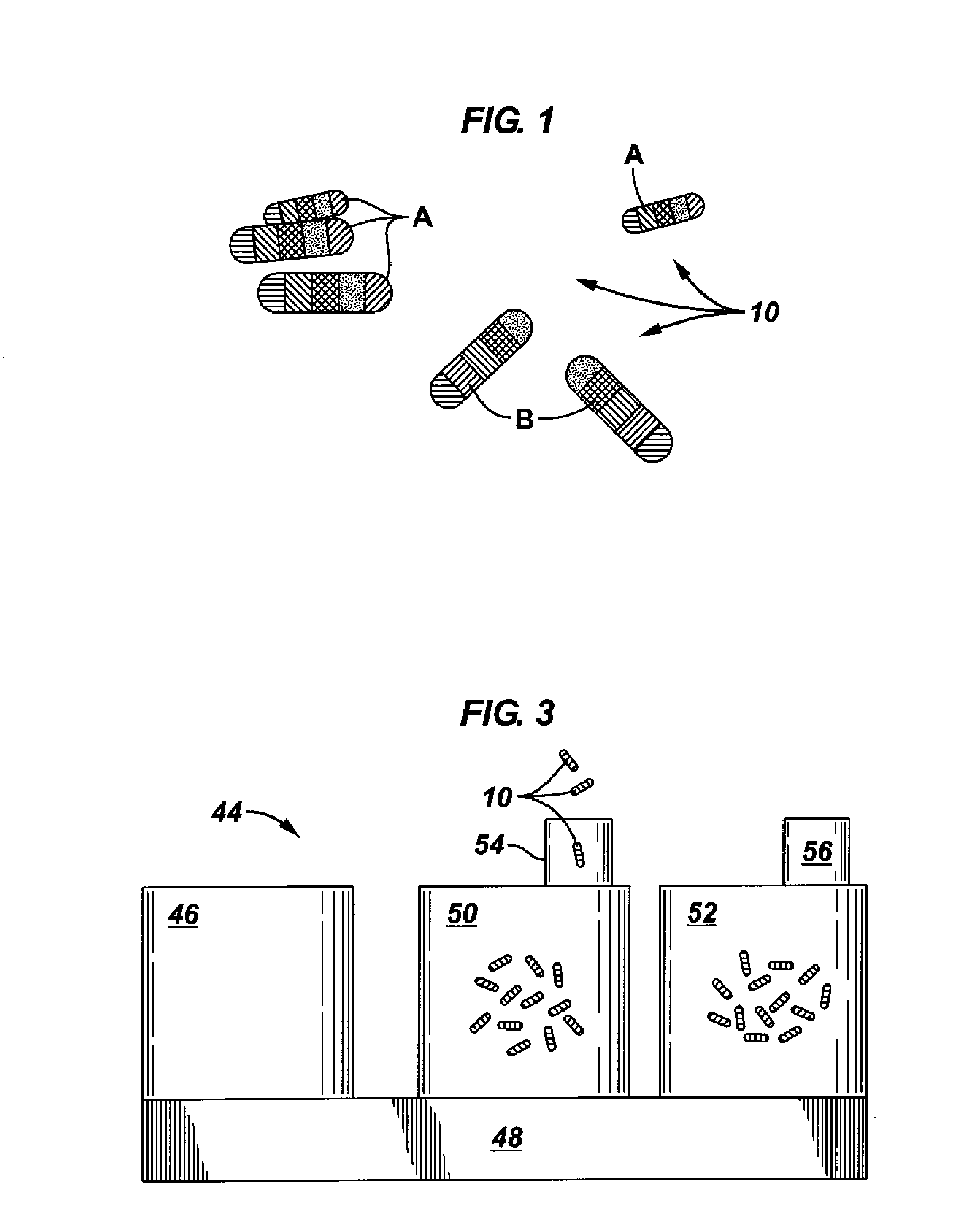
[0025]Embodiments of the present invention relate to coded particle technology. Embodiments of the invention use small particles doped with different substances, such as rare earth elements, that can provide an unique optical emission when excited with a light source (e.g., with an appropriate wavelength radiation). In accordance with some embodiments of the invention, rare earth-doped glasses are chosen because of their narrow emission bands, high quantum efficiencies, non-interference with common fluorescent labels, and inertness to most organic and aqueous solvents. These properties and the large number of possible combinations of these microbarcodes make them attractive for use in subsurface or downhole applications.

[0026]Embodiments of the invention may be based in part on the coded particle technology described in M. J. Dejneka et al., Optically active glasses for biology, 3-D display, and telecommunications, Proceedings of the XX ICG International Congress on Glass, Kyoto, Se...


PUM


Abstract

A tagged object includes a main body and a plurality of coded particles. Each coded particle may have a miniature body and be configured to provide a resolvable optical emission pattern when illuminate. The plurality of coded particles may be immobilized to the main body. A method for performing oilfield monitoring may include disposing of different types of tagged objects at different locations, wherein the different types of tagged objects each comprise a plurality of coded particles. Each of the coded particles may have a miniature body containing rare earth elements configured to produce a unique optical emission pattern when illuminated. The method may include allowing an event to trigger the release of one of the different types of tagged objects from one of the different locations. In addition, the method may include identifying the released tagged objects by unique optical emission patterns, in some cases in order to determining an occurrence location of the event.

Description

CROSS-REFERENCE TO RELATED APPLICATIONS[0001]This application is a Continuation-In-Part of U.S. patent application Ser. No. 11 / 863,598, filed Sep. 28, 2007, and claims the benefit of U.S. Provisional Application Ser. No. 60 / 990,642, filed Nov. 28, 2007, both of which are incorporated herein by reference in their entirety.BACKGROUND OF INVENTION[0002]1. Field of the Invention[0003]The present invention relates generally to the field of tracers or marker materials. More specifically, the invention relates to subsurface tagging and monitoring techniques.[0004]2. Background Art[0005]Tracers have been used in the oil and gas industry for many years. One use of the tracers is to determine the “lag time” for the drilling fluid (“mud”) to travel from the surface down the borehole, through the drill bit, and up to the surface again. A conventional technique for this purpose involves the use of calcium carbide pellets that have been enclosed in a water-proof container. Such carbide pellets ar...

Claims


Application Information

Patent Timeline
IPC IPC(8): G01N33/24E21B47/10
CPCC09K8/032C09K8/80C09K8/805G01N33/2823E21B47/1015E21B47/102E21B43/267E21B47/113E21B47/11E21B47/114E21B47/00G01V15/00
Inventor RAMOS, ROGERIO T.COOPER, IAINBROWN, J. ERNEST
Owner SCHLUMBERGER TECH CORP
Why Eureka
Try Eureka