Mri-compatible head fixation frame with cooperating head coil apparatus

a technology of head fixation frame and cooperating head coil, which is applied in the field of medical systems and apparatus, can solve the problems of reduced efficacy, long duration of procedures, and clinical efficacy less than optimal of devices/procedures, and achieves the effect of convenient adjustmen

Inactive Publication Date: 2009-04-02
MRI INTERVENTIONS INC
View PDF12 Cites 38 Cited by
  • Summary
  • Abstract
  • Description
  • Claims
  • Application Information

AI Technical Summary

Benefits of technology

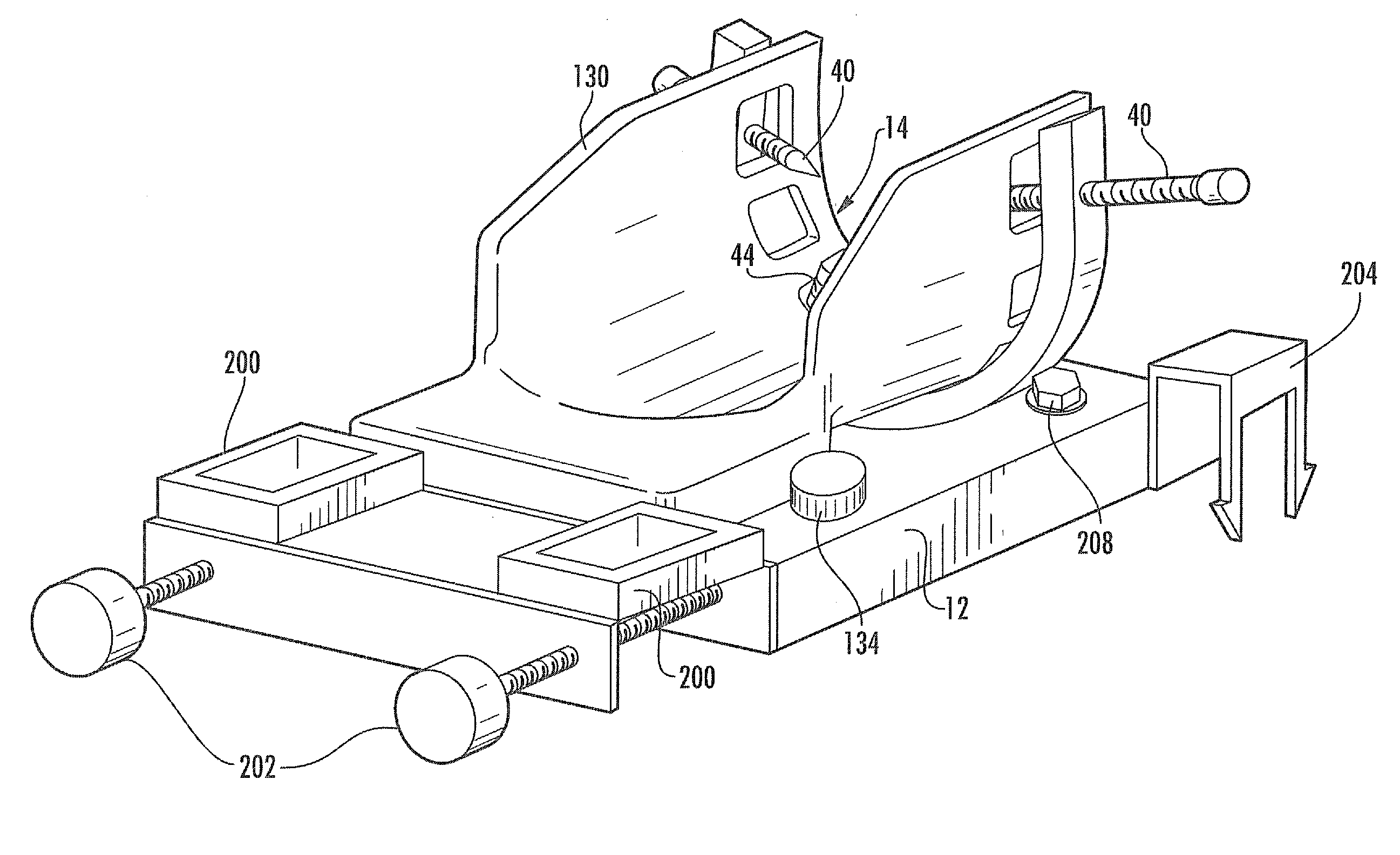
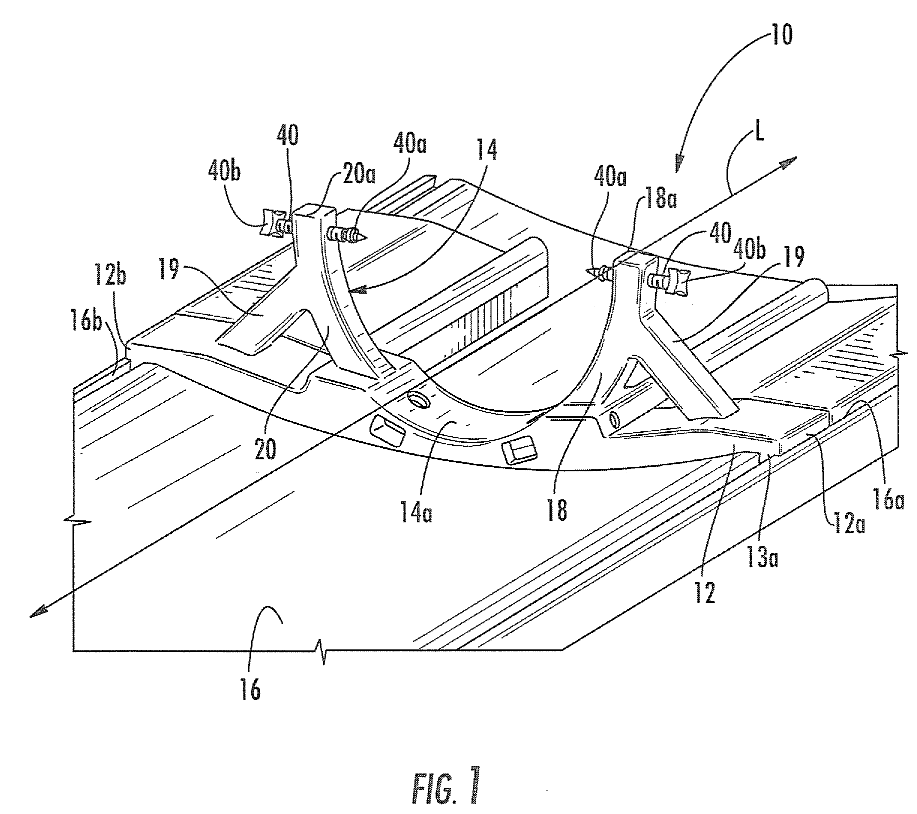
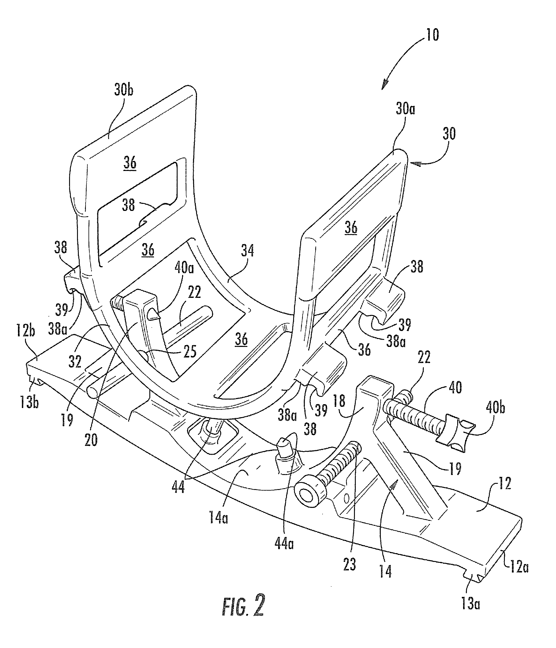
[0011]The head coil apparatus includes a plurality of spaced-apart RF coils, and is configured to surround at least a portion of a patient's head supported by the head support frame. The head coil apparatus has a substantially open-face, U-shaped configuration with spaced-apart leg portions having free ends. The head coil apparatus can be adjustably secured to the head support frame between the head support frame arms such that leg portion free ends extend upwardly. Also, the head coil apparatus can be adjustable along a longitudinal direction relative to the head support frame. The open-face configuration of the head coil apparatus facilitates access to a patient by a physician / clinician, and / or interventional tools while providing sufficient signal-to-noise ratio (SNR) MRI signals.
[0012]In some embodiments, the head coil apparatus includes a pair of longitudinally spaced-apart, U-shaped supports, and a plurality of spaced apart members extending longitudinally between the supports. RF coils are associated with the spaced-apart members. In other embodiments, the head coil apparatus has a substantially unitary structure with a plurality of spaced-apart access windows formed therein. In some embodiments, the head coil apparatus has a flared or tapered end portion that further facilitates access to a patient by a physician / clinician.
[0016]In some embodiments, a shield may be removably secured to the head support frame and is configured to shield non-MRI compatible objects used in conjunction with the head support assembly during an MRI-guided procedure. For example, cables and other conductive materials and devices utilized in a medical procedure can be shielded from RF excitation via the shield. The shield can be configured to protect against liquids, such as blood, and other materials that may cause damage to cables and electronic equipment, etc.
[0018]The head coil apparatus includes a plurality of spaced-apart RF coils, and is configured to surround at least a portion of a patient's head supported by the head support frame. The head coil apparatus has a substantially open, U-shaped open-face configuration with spaced-apart leg portions having free ends. The head coil apparatus is adjustably secured to the head support frame between the head support frame arms such that leg portion free ends extend upwardly. Also, the head coil apparatus can be adjustable along a longitudinal direction relative to the head support frame for improved alignment to intrabody (deep brain, etc.) locations of various patient head sizes.
[0022]Head support assemblies according to embodiments of the present invention can be advantageous over conventional systems because they can be easily adjustable for various patient head sizes and shapes, and can support large forces exerted in any direction without movement, thereby providing stability to the head of a patient during various interventional procedures. In addition, head support assemblies according to embodiments of the present invention do not allow a patient's head to move in any direction, including pivotal movement. Moreover, head support assemblies according to embodiments of the present invention do not interfere with other components or a physician's access to the patient. Head support assemblies, according to embodiments of the present invention can be sterilized within an autoclave, and can be wiped down with disinfectant and cleaners. Head support assemblies, according to embodiments of the present invention can be installed and used many times without degradation, or may be single-use and disposable.

Problems solved by technology

These procedures can be long in duration and may have reduced efficacy as it has been reported that, in about 30% of the patients implanted with these devices, the clinical efficacy of the device / procedure is less than optimum.

Method used


Image

  • Mri-compatible head fixation frame with cooperating head coil apparatus
  • Mri-compatible head fixation frame with cooperating head coil apparatus
  • Mri-compatible head fixation frame with cooperating head coil apparatus

Examples


Embodiment Construction

[0043]The present invention now is described more fully hereinafter with reference to the accompanying drawings, in which some embodiments of the invention are shown. This invention may, however, be embodied in many different forms and should not be construed as limited to the embodiments set forth herein; rather, these embodiments are provided so that this disclosure will be thorough and complete, and will fully convey the scope of the invention to those skilled in the art.

[0044]Like numbers refer to like elements throughout. In the figures, the thickness of certain lines, layers, components, elements or features may be exaggerated for clarity.

[0045]The terminology used herein is for the purpose of describing particular embodiments only and is not intended to be limiting of the invention. As used herein, the singular forms “a”, “an” and “the” are intended to include the plural forms as well, unless the context clearly indicates otherwise. It will be further understood that the term...


PUM


Abstract

A head support assembly includes a base configured to be removably secured to an MRI scanner gantry, a head support frame attached to the base, and a longitudinally extending head coil apparatus adjustably secured to the head support frame. The head support frame includes a pair of elongated arms that extend outwardly in adjacent, spaced-apart, substantially co-planar relationship to form an area for receiving the head of a patient. Each arm includes a respective free end, and a head engagement rod is adjustably associated with each respective arm free end. The head engagement rods are configured to engage a patients head within the head support frame. One or more additional head engagement rods may extend outwardly from the head support frame between the pair of arms.

Description

RELATED APPLICATIONS[0001]This application claims the benefit of and priority to U.S. Provisional Patent Application No. 60 / 974,821, filed Sep. 24, 2007, and U.S. patent application Ser. No. 12 / 134,412, filed Jun. 6, 2008, the disclosures of which are incorporated herein by reference as if set forth in their entireties.FIELD OF THE INVENTION[0002]The present invention relates generally to medical systems and apparatus and, more particularly, to MRI-interventional systems and apparatus.BACKGROUND[0003]Deep Brain Stimulation (DBS) is becoming an acceptable therapeutic modality in neurosurgical treatment of patients suffering from chronic pain, Parkinson's disease or seizure, and other medical conditions. Other electro-stimulation therapies have also been carried out or proposed using internal stimulation of the sympathetic nerve chain and / or spinal cord, etc. One example of a prior art DBS system is the Activa® system from Medtronic, Inc. The Activa® system includes an implantable pul...

Claims


Application Information

Patent Timeline
Patent Type & Authority Applications(United States)
IPC IPC(8): G01R33/34
CPCA61B5/055A61B5/0555A61B19/201A61B19/203A61B19/50A61B2019/208G01R33/3415A61B2019/5236A61B2019/5433A61B2019/5437A61B2019/545A61B2019/5454G01R33/34046A61B2019/501A61B34/10A61B90/11A61B90/14A61B2034/101A61B2090/103A61B2090/374A61B2090/3933A61B2090/3937A61B2090/395A61B2090/3954
Inventor PIFERI, PETERKEIDL, CHRISTOPHERPETERSON, DAVID
Owner MRI INTERVENTIONS INC
Why Eureka
Try Eureka