Supercritical steam combined cycle and method

a combined cycle and supercritical steam technology, applied in steam engine plants, hot gas positive displacement engine plants, machines/engines, etc., can solve the problems of significant irreversibility in the cycle, limited performance of the current bottoming cycle technology (mostly sub-critical pressure), and performance gains not big enough to justify the additional cost of combined cycle applications. , to achieve the effect of enhancing economic feasibility, reducing irreversibility of energy transfer, and improving combined cycle performan

Active Publication Date: 2009-04-09
GENERAL ELECTRIC CO
View PDF20 Cites 29 Cited by
  • Summary
  • Abstract
  • Description
  • Claims
  • Application Information

AI Technical Summary

Benefits of technology

[0007]The invention disclosed herein further reduces the irreversibility of energy transfer with optimum placement of HRSG heat transfer sections, allowing significantly better combined cycle performance from supercritical cycles. This additional performance will substantially enhance the economic feasibility of supercritical steam cycle based combined cycles.

Problems solved by technology

The performance of the current bottoming cycle technology (mostly sub-critical pressure) is limited by the pinch points which occur in the HRSG evaporators due to constant temperature phase change from water to steam, with heat equal to the latent heat of vaporization required for this process.
This discontinuity in temperature causes a mismatch between the gas turbine exhaust gas and the water / steam heating, resulting in significant irreversibility in the cycle.
This behavior and benefit has been known in the past, but the performance gains were not big enough to justify the additional cost in combined cycle applications.

Method used


Image

  • Supercritical steam combined cycle and method
  • Supercritical steam combined cycle and method
  • Supercritical steam combined cycle and method

Examples


Embodiment Construction

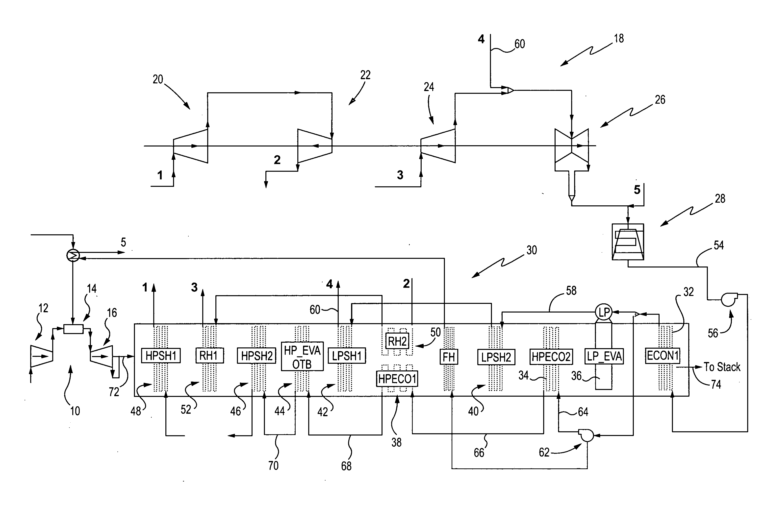
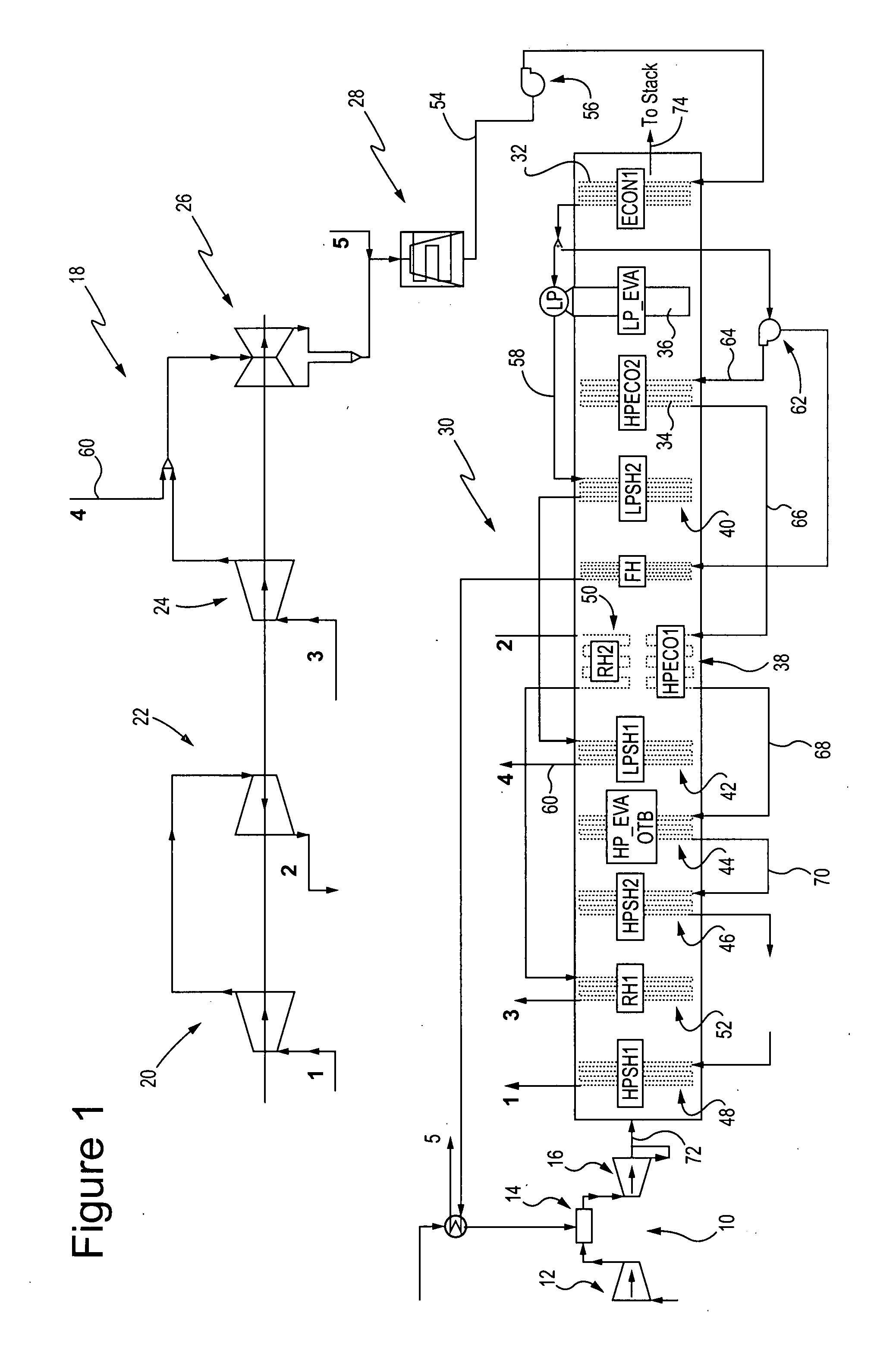
[0013]The current practice of optimal reheat configuration for single pressure or multi pressure supercritical steam cycles is with the reheat section of the HRSG placed upstream of the “HP_EVA OTB” (high pressure supercritical evaporator once through boiler) section with respect to the exhaust gas flow.

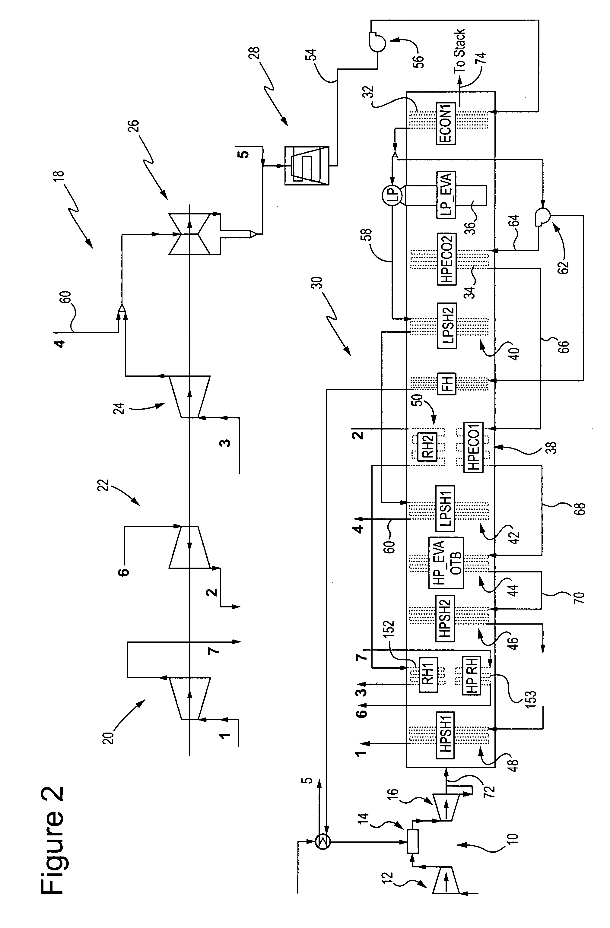
[0014]An embodiment of the present invention provides a two stage reheat configuration, with one reheat section upstream, and the other downstream of the phase change point (water to steam transition at critical steam temperature) of the high pressure (supercritical) HRSG section.

[0015]The inventive concept may be incorporated in a single pressure or a multi-pressure supercritical steam cycle. A schematic of a two pressure supercritical steam cycle power generation system embodying the invention is shown in FIG. 1.

[0016]This example includes a gas turbine system 10 comprising a compressor 12, a combustion system 14, a gas turbine 16, and a steam turbine system 18 including a supercri...


PUM


Abstract

A supercritical steam combined cycle system including a gas turbine; a supercritical steam turbine system including a supercritical section, a high pressure section, an intermediate pressure section and at least one low pressure section; and a supercritical steam heat recovery steam generator (HRSG) for receiving exhaust gas from the gas turbine for heating fluid from the steam turbine system. The HRSG includes a supercritical evaporator arranged to supply steam to a superheater between the supercritical evaporator and the inlet of the HRSG and a reheater receiving cold reheat steam from and returning reheated steam to the steam turbine system. The reheater includes a first section disposed downstream of and a second section disposed upstream of the supercritical evaporator along the exhaust gas flow path. Cool reheat steam from the steam turbine system is received by the first reheater section and steam leaving the first reheater section is supplied to the second reheater section upstream of the supercritical evaporator.

Description

BACKGROUND OF THE INVENTION[0001]The invention relates to a method of heat integration and optimum configuration for a single or multi pressure level Supercritical Steam Heat Recovery Steam Generator (HRSG) with reheat used in combined cycle applications.[0002]The most commonly applied steam bottoming cycles for combined cycle power plants currently being installed and operated are reheat steam cycles with sub-critical steam generation at multiple pressures and a single reheater located in the heat recovery steam generator gas path upstream of the high pressure evaporator. This combined cycle configuration was first described in a paper, “GE MS7001FCombined-Cycle Power Plant” by Leroy O. Tomlinson, Roger O. Anderson and Raub W. Smith that was presented to the American Power Conference in April, 1987 and published in the proceedings of this conference. The current state of the art irreversibility losses are ˜10% of GT exhaust energy.[0003]Performance of combined cycles with the rehea...

Claims


Application Information

Patent Timeline
Patent Type & Authority Applications(United States)
IPC IPC(8): F02C6/04
CPCY02E20/16F01K23/106
Inventor TOMLINSON, LEROY OMARSMITH, RAUB WARFIELDRANASINGHE, JATILAGULEN, SEYFETTIN CANRANCRUEL, DIEGO FERNANDO
Owner GENERAL ELECTRIC CO
Why Eureka
Try Eureka