Separation method and device for coupling type alkane catalytic dehydrogenation reaction product

A technology for catalytic dehydrogenation and reaction products, applied in chemical instruments and methods, fractional condensation purification/separation, cold treatment separation, etc., can solve the problem of poor separation effect of propane dehydrogenation reaction gas, low C3 recovery rate, and complex unit. and other problems, to achieve the effect of saving separation energy consumption, reducing irreversibility and loss, and reducing separation energy consumption

Pending Publication Date: 2022-06-03
WISON ENG
View PDF0 Cites 0 Cited by
  • Summary
  • Abstract
  • Description
  • Claims
  • Application Information

AI Technical Summary

Problems solved by technology

[0006] The present invention provides a separation method and device for a coupled alkane catalytic dehydrogenation reaction product, which overcomes the poor separation effect of propane dehydrogenation reaction gas, high energy consumption, low C3 recovery rate and complicated unit in the prior art. defect

Method used


Image

  • Separation method and device for coupling type alkane catalytic dehydrogenation reaction product
  • Separation method and device for coupling type alkane catalytic dehydrogenation reaction product
  • Separation method and device for coupling type alkane catalytic dehydrogenation reaction product

Examples


Embodiment 1

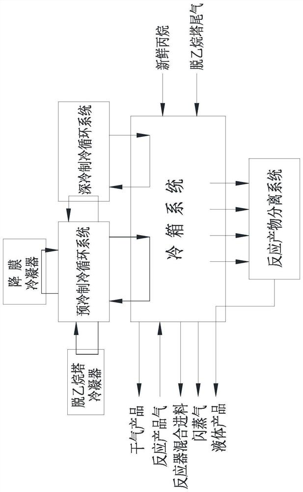
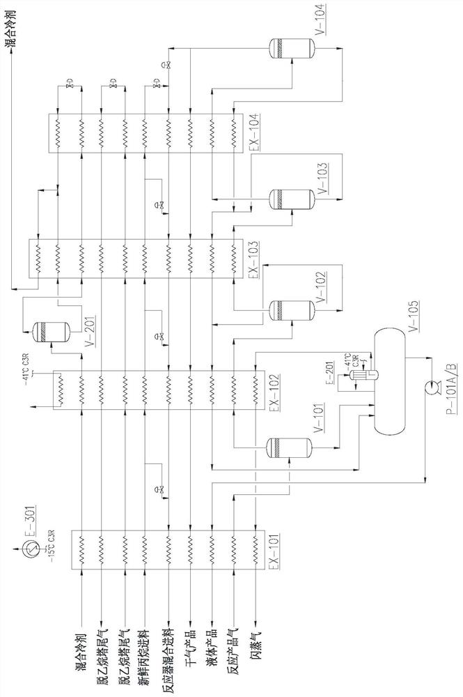
[0061] like figure 2 As shown in the figure, the reaction product gas at the outlet of the propane dehydrogenation reactor enters the separation system plate-fin heat exchanger EX-101 after pretreatment such as cooling, compression, purification and filtration. Separation tank V101, the separated liquid phase enters the carbon three product tank V-105, and the gas phase enters the plate-fin heat exchanger EX-102 for further cooling and condensing to -38 ℃ and then enters the gas-liquid separation tank V-102. After the phase carbon three is mixed with the liquid phase carbon three separated from the next stage, it is reheated in the plate-fin heat exchanger EX-102 and aggregated to the carbon three product tank V-105 by its own pressure, and the gas phase enters the plate-fin heat exchange. After further cooling and condensation in the heat exchanger EX-103, it enters the gas-liquid separation tank V-103. The separated liquid phase carbon three is separated from the next stage...

Embodiment 2

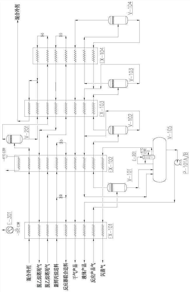
[0066] like image 3 As shown in the figure, the reaction product gas at the outlet of the propane dehydrogenation reactor enters the separation system plate-fin heat exchanger EX-101 after pretreatment such as cooling, compression, purification and filtration. Separation tank V101, the separated liquid phase enters the carbon three product tank V-105, and the gas phase enters the plate-fin heat exchanger EX-102 for further cooling and condensing to -37°C and then enters the gas-liquid separation tank V-102. After the phase C3 is mixed with the liquid C3 separated from the next stage, it is reheated in EX-102 and collected to the C3 product tank V-105 by its own pressure, and the gas phase enters the plate-fin heat exchanger EX-103 for further cooling After condensing, it enters the gas-liquid separation tank V-103, and the separated liquid-phase carbon three is mixed with the liquid-phase carbon three separated from the next stage and reheated in the plate-fin heat exchanger ...

Embodiment 3

[0071] like Figure 4 As shown, the reaction product gas at the outlet of the propane dehydrogenation reactor enters the separation system plate-fin heat exchanger EX-101 after pretreatment such as cooling, compression, purification and filtration. Separation tank V101, the separated liquid phase enters the carbon three product tank V-105, and the gas phase enters the plate-fin heat exchanger EX-102 for further cooling and condensing to -30 ℃, and then enters the gas-liquid separation tank V102, the separated liquid phase carbon The carbon three separated from the next stage and reheated in the plate-fin heat exchanger EX-103 is mixed, and then reheated in the plate-fin heat exchanger EX-102 and aggregated to the carbon three product by its own pressure Tank V-105, the gas phase enters the plate-fin heat exchanger EX-103, and after cooling to -130 ℃, it enters the gas-liquid separation tank V-103. The dry gas and circulating gas are obtained at the top of the final gas-liquid...


PUM


Abstract

The invention relates to a method and a device for separating a coupled alkane catalytic dehydrogenation reaction product, and the method comprises the following steps: inputting product gas at an outlet of an alkane dehydrogenation reactor into a cold box system to obtain a cooled product; the cooled product is input into N stages of gas-liquid separation tanks connected in series for gas-liquid separation, and then gas-phase products obtained from the first stage to the (N-1) th stage are input into the cold box system again; liquid-phase products obtained at the 1-N stages are collected, reheated and sent out of a boundary area, and then separation of products with different carbon numbers of the liquid-phase products is achieved through a separation tower; circulating gas obtained at the top of the Nth-stage separation tank and fresh propane are subjected to M-stage mixing according to a preset hydrogen / hydrocarbon ratio and subjected to throttling evaporation in a cold box system, and cold energy is provided for the cold box system; introducing the tail gas at the top of the dethanizer into a cold box system, and providing cold energy for the cold box system; and the cold energy of the cold box system also comes from an external refrigeration cycle system. Separation energy consumption can be reduced, product loss is reduced, the technological process is simple and environmentally friendly, equipment is compact, and starting / stopping is convenient and fast.

Description

technical field [0001] The invention relates to the technical field of chemical separation, in particular to a separation method and device for a coupled alkane catalytic dehydrogenation reaction product. Background technique [0002] With the participation of catalysts, alkanes can undergo dehydrogenation reactions to generate higher value-added alkenes and hydrogen. Among all kinds of olefins, propylene is an important petrochemical basic raw material. It is mainly used to produce dozens of petrochemical products and raw materials such as polypropylene, propylene oxide, acrylic acid, acrylonitrile, alkylated oil, and high-octane gasoline blending material. In recent years, due to the rapid development of various chemical products downstream of propylene, the domestic demand for propylene has continued to grow rapidly. [0003] For a long time, propylene has mainly come from the steam cracking process of naphtha and the catalytic cracking process of petroleum refining. I...

Claims


Application Information

Patent Timeline
IPC IPC(8): C07C11/06C07C5/333C07C7/09F25J5/00
CPCC07C5/333C07C7/09F25J5/00C07C11/06F25J3/062F25J2210/62F25J2235/60F25J2270/12F25J2245/02F25J3/0645F25J2270/904F25J2210/12F25J3/0655F25J2270/60F25J2270/66F25J2270/18F25J2260/02
Inventor 吴笛吴铁锁田靖丁干红吕建宁李延生
Owner WISON ENG
Why Eureka
Try Eureka