Rotational-flow purifying device for gaseous product in fluidized-bed residual oil hydrogenation reactor and method for purifying gaseous product by same

A hydrogenation reactor and purification device technology, applied in chemical instruments and methods, separation methods, dispersed particle separation, etc., can solve problems such as reducing energy consumption of ebullating bed hydrogenation devices, reducing heat exchange efficiency, and extending operating cycles, etc. Achieve the effects of prolonging the continuous operation period, high precision of cyclone separation, and large separation operation space

Active Publication Date: 2014-04-02
CHINA PETROLEUM & CHEM CORP +2
View PDF12 Cites 8 Cited by
  • Summary
  • Abstract
  • Description
  • Claims
  • Application Information

AI Technical Summary

Problems solved by technology

[0009] The purpose of the present invention is to overcome the defects existing in the prior art, and to provide a gas phase product swirling purification device of an ebullated bed residue hydrogenation reactor, so that it can clean the liquid entrained in the gas phase product of the ebullated bed residue hydrogenation reactor. Droplets and solid particles are separated by cascade cyclone according to particle size, reducing the amount of liquid entrainment and catalyst solid particle entrainment in the gas phase product going to the cold high-pressure separation process, and avoiding the problem of high-pressure heat exchanger clogging or heat exchange efficiency decline, which is extremely Greatly reduce the energy consumption of the fluidized bed hydrogenation unit, and effectively extend the operation period of the unit

Method used


Image

  • Rotational-flow purifying device for gaseous product in fluidized-bed residual oil hydrogenation reactor and method for purifying gaseous product by same
  • Rotational-flow purifying device for gaseous product in fluidized-bed residual oil hydrogenation reactor and method for purifying gaseous product by same
  • Rotational-flow purifying device for gaseous product in fluidized-bed residual oil hydrogenation reactor and method for purifying gaseous product by same

Examples


Embodiment Construction

[0030] The present invention will be further described below in conjunction with the accompanying drawings and embodiments.

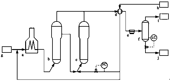
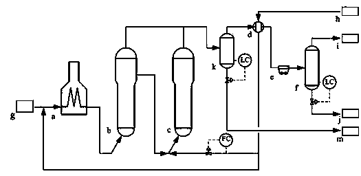
[0031] Such as figure 1 with figure 2 , figure 1 It is a schematic diagram of the gas phase product purification device of the existing fluidized bed residual oil hydrogenation reactor. The gas phase product purification process of the existing fluidized bed residual oil hydrogenation reactor: the raw material residual oil enters the heating furnace through the raw material residual oil input port g After a is heated, it enters the first residue ebullating bed hydrogenation reactor b for hydrocracking, and the liquid phase product of the first residue ebullating bed hydrogenation reactor b is mixed with mixed hydrogen and then enters the second residue ebullating bed hydrogenation Reactor c undergoes hydrocracking, and the gas phase products of the first residual oil ebullating bed hydrogenation reactor b and the second residual oil ebullating long h...


PUM


Abstract

The invention relates to a rotational-flow purifying device for a gaseous product in a fluidized-bed residual oil hydrogenation reactor. The device comprises the fluidized-bed residual oil hydrogenation reactor and a thermal high-pressure gas/hydrogen heat exchanger, wherein a thermal high-pressure flash tank is arranged between the reactor and the heat exchanger, and comprises a thermal high-pressure flash tank shell and an inlet distribution ring arranged in the shell; the inlet distribution ring has a spiral structure and defines a spiral channel together with the thermal high-pressure flash tank shell; a gaseous product inlet is formed in the thermal high-pressure flash tank shell; a tangential inlet guide pipe is mounted on the gaseous product inlet; the thermal high-pressure flash tank also comprises a micro-rotational-flow separator set arranged at the top in the thermal high-pressure flash tank shell. According to the device, the gaseous product in the fluidized-bed residual oil hydrogenation reactor is subjected to stepped rotational-flow separation, so that the entrainment quantity of liquid and catalysts in the gaseous product during a cold high-pressure separation process is reduced, the problem of blockage of the high-pressure heat exchanger is avoided, the energy consumption of a fluidized-bed hydrogenation device is greatly reduced, and the running cycle of the device is prolonged.

Description

technical field [0001] The invention relates to a cyclone purification device for gas phase products of a fluidized bed residual oil hydrogenation reactor, belonging to the technical field of petroleum processing. Background technique [0002] The ebullating bed hydrogenation reactor belongs to the gas, liquid and solid three-phase fluidized bed reactor, which can process heavy oil with high sulfur, high carbon residue and high metal. It has obvious advantages in problems such as quick work, large system pressure drop, easy coking, and short operation period of the device. [0003] Since the materials in the ebullated bed reactor are in a state of full back-mixing, the catalyst particles and liquid phase reaction products will be taken out of the reactor by the gas phase products at the top of the reactor, and entrained into the equipment in the subsequent cold and high pressure separation process and In the pipeline, the heat exchange efficiency of the high-pressure heat e...

Claims


Application Information

Patent Timeline
Patent Type & Authority Applications(China)
IPC IPC(8): B01D45/16
Inventor 李剑平高跃李立权陈崇刚曾茜赵颖许德建汪华林唐超
Owner CHINA PETROLEUM & CHEM CORP
Why Eureka
Try Eureka