Fuel Cell System
a fuel cell and system technology, applied in the field of fuel cell systems, can solve the problems of large heat amount, difficult to perform stable power generation, disadvantages of structure in air supply and heat radiation, etc., and achieve the effect of solving the shortage of humidity, suppressing flooding, and solving flooding
- Summary
- Abstract
- Description
- Claims
- Application Information
AI Technical Summary
Benefits of technology
Problems solved by technology
Method used
Image
Examples
first example
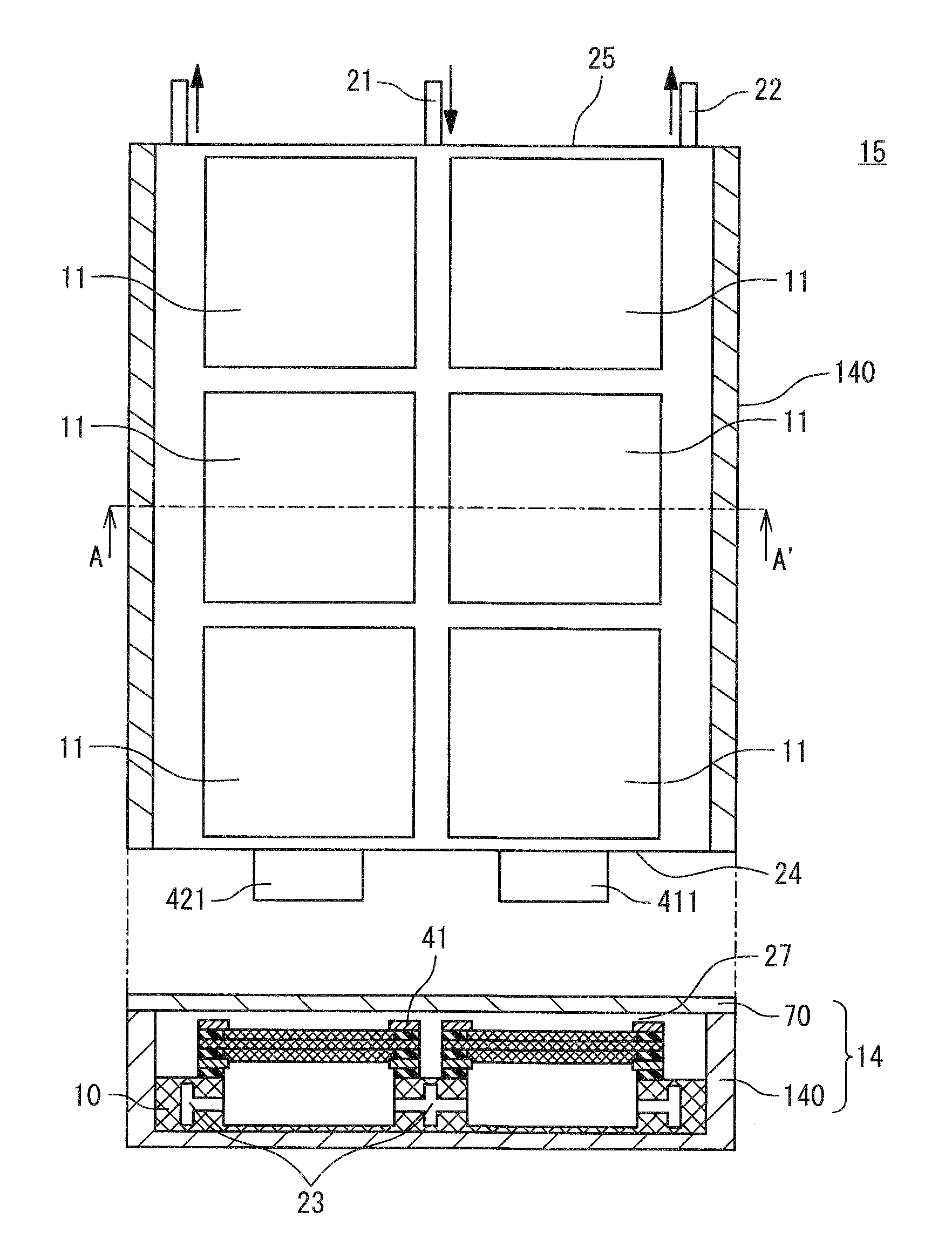
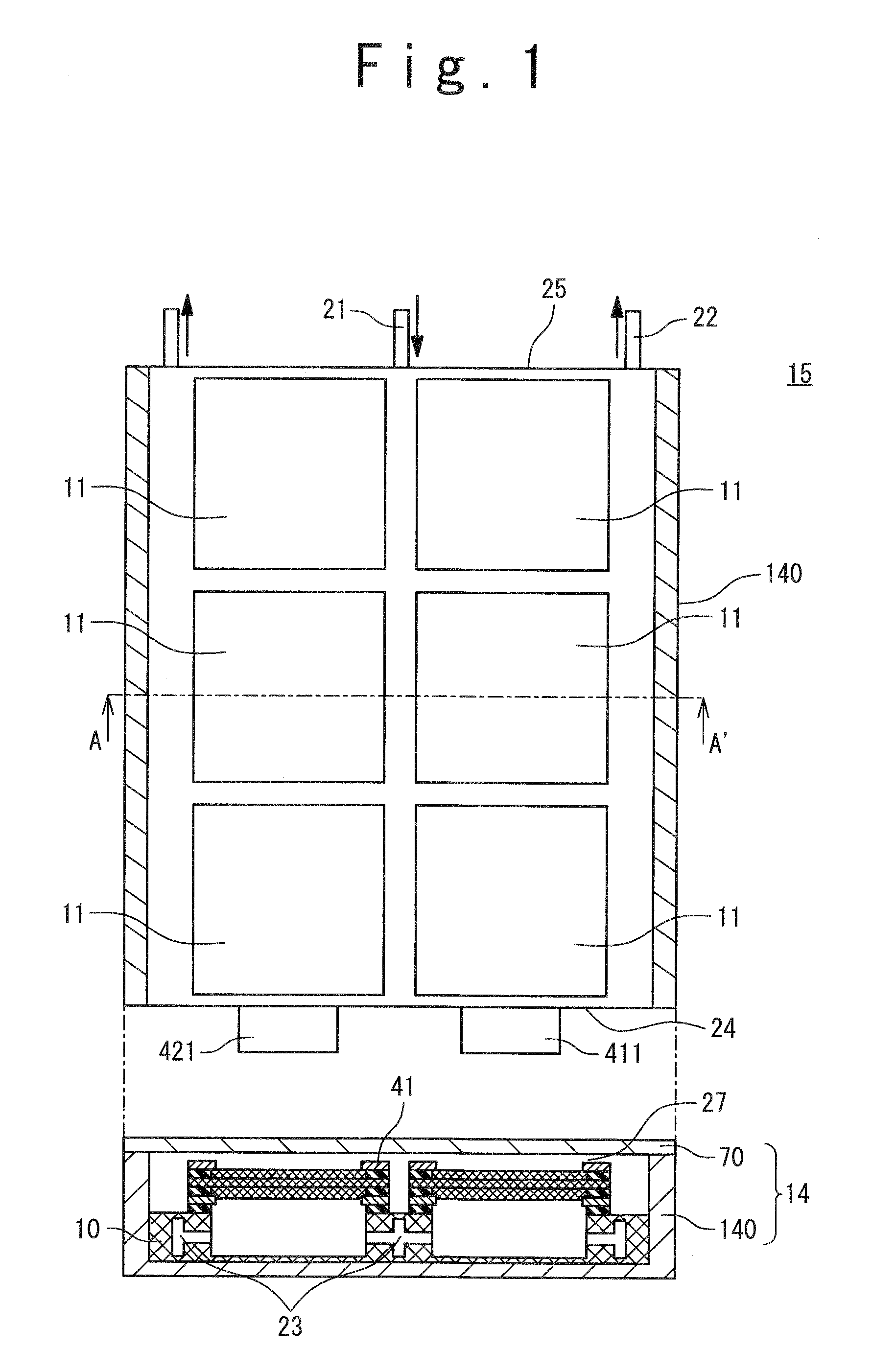
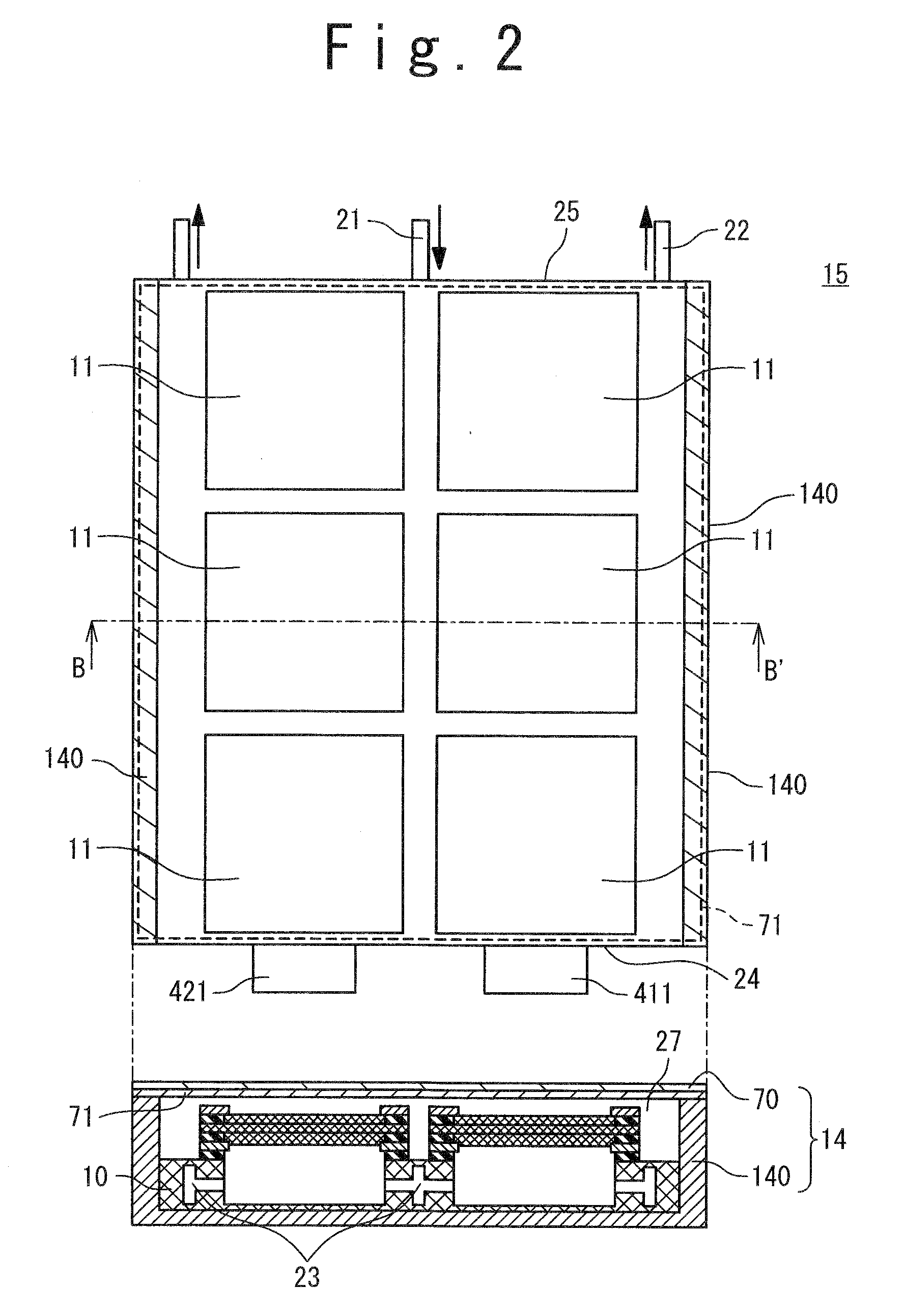
[0112]A structure of a fuel cell used in a first example will be explained below. In the present example, the fuel cell system 1 shown in FIG. 2 is manufactured.
[0113]At first, catalyst-supporting carbon fine particles which supports platinum fine particles with a particle diameter within a range from 3 to 5 nm at 50% ratio by weight on carbon particles (the KETJENBLACK EC600JD manufactured by LION Co.) was prepared. By adding 5% by weight of Nafion solution (name of commodity; DE521, the “Nafion” is a registered trade mark of Dupont Co.) into 1 g of the catalyst-supporting carbon fine particles and agitating the solution, catalyst paste for forming the cathode was obtained. By coating the catalyst paste on carbon paper (TGP-H-120 manufactured by Toray Co.) as a substrate at a coating amount from 1 to 8 mg / cm2 and drying it, the cathode 31 of 4 cm×4 cm was manufactured. Meanwhile, a catalyst paste for forming an anode was obtained under a same condition as that in obtaining the cata...
second example
[0121]A structure of a unit fuel cell used in a second example will be explained below. A manufacturing method and a structure of the MEA are the same as those of the first example, and a structure of the fuel cell stack 15 is also the same as that of the first example. Other conditions are also the same if not other mentioned below.
[0122]As for the second example, the fuel cell system 1 shown in FIG. 3 was manufactured. That is, only arrangement of the mesh 71 in the first example was changed. A size of the mesh 71 is 20 cm long side×14.5 cm short side so that the mesh 71 cannot be sandwiched between the partitions provided on both sides of the chassis body 140 and the lid 70.
third example
[0123]A structure of a unit fuel cell used in a third example will be explained below. A manufacturing method and a structure of the MEA are the same as those of the first example, and a structure of the fuel cell stack 15 is also the same as that of the first example. Other conditions are also the same if not other mentioned below.
[0124]As for the third example, the fuel cell system shown in FIG. 4 was manufactured. That is, the shape of the mesh in the first example was changed. A size of the mesh is 20 cm long side×14.5 cm short side so that the mesh 71 cannot be sandwiched between the partitions provided on both sides of the chassis body 140 and the lid 70. Furthermore, in a clearance between the unit fuel cells 11 forming two rows, the mesh 71 is divided with keeping a clearance of 0.5 cm.
PUM
 Abstract
Description
Claims
Application Information
 - R&D
- Intellectual Property
- Life Sciences
- Materials
- Tech Scout
- Unparalleled Data Quality
- Higher Quality Content
- 60% Fewer Hallucinations
Browse by: Latest US Patents, China's latest patents, Technical Efficacy Thesaurus, Application Domain, Technology Topic, Popular Technical Reports.
© 2025 PatSnap. All rights reserved.Legal|Privacy policy|Modern Slavery Act Transparency Statement|Sitemap|About US| Contact US: help@patsnap.com


