Fuel cell system

a fuel cell and system technology, applied in the field of fuel cell systems, can solve the problems of large heat amount, difficult to perform stable power generation, disadvantages of structure in air supply and heat radiation, etc., and achieve the effect of solving the shortage of humidity, suppressing flooding, and solving flooding

Inactive Publication Date: 2012-10-02
NEC CORP
View PDF28 Cites 0 Cited by
  • Summary
  • Abstract
  • Description
  • Claims
  • Application Information

AI Technical Summary

Benefits of technology

[0025]The present invention is proposed in order to solve the above-mentioned problems. That is, an object of the present invention is to provide a fuel cell system suppressing the flooding in which the condensation water interferes the power generation, in the fuel cell system having a plurality of unit fuel cells such as the planar stack type fuel cell system.
[0041]According to the present invention, the fuel cell system is further provided, which suppresses the flooding and solves the shortage of humidity after achieving reduction of the space required by the portable device.

Problems solved by technology

In addition, when electric power consumption becomes large, a heat amount also becomes large.
Accordingly, when a structure where the separator is provided on the cathode and a part of the space over the cathode is separated is employed, the structure has disadvantages in the air supply and the heat radiation.
However, in the fuel cell system consuming large electric power, the air flowing in the air flow space have to pass on many unit fuel cells from an aspirating portion to an exhausting portion.
In such situation, a portion where a power generation environment is in low temperature and low humidity and a portion where a power generation environment is in high temperature and high humidity exist together in an identical fuel cell stack, thus it becomes difficult to perform the stable power generation.

Method used


Image

  • Fuel cell system
  • Fuel cell system
  • Fuel cell system

Examples


first example

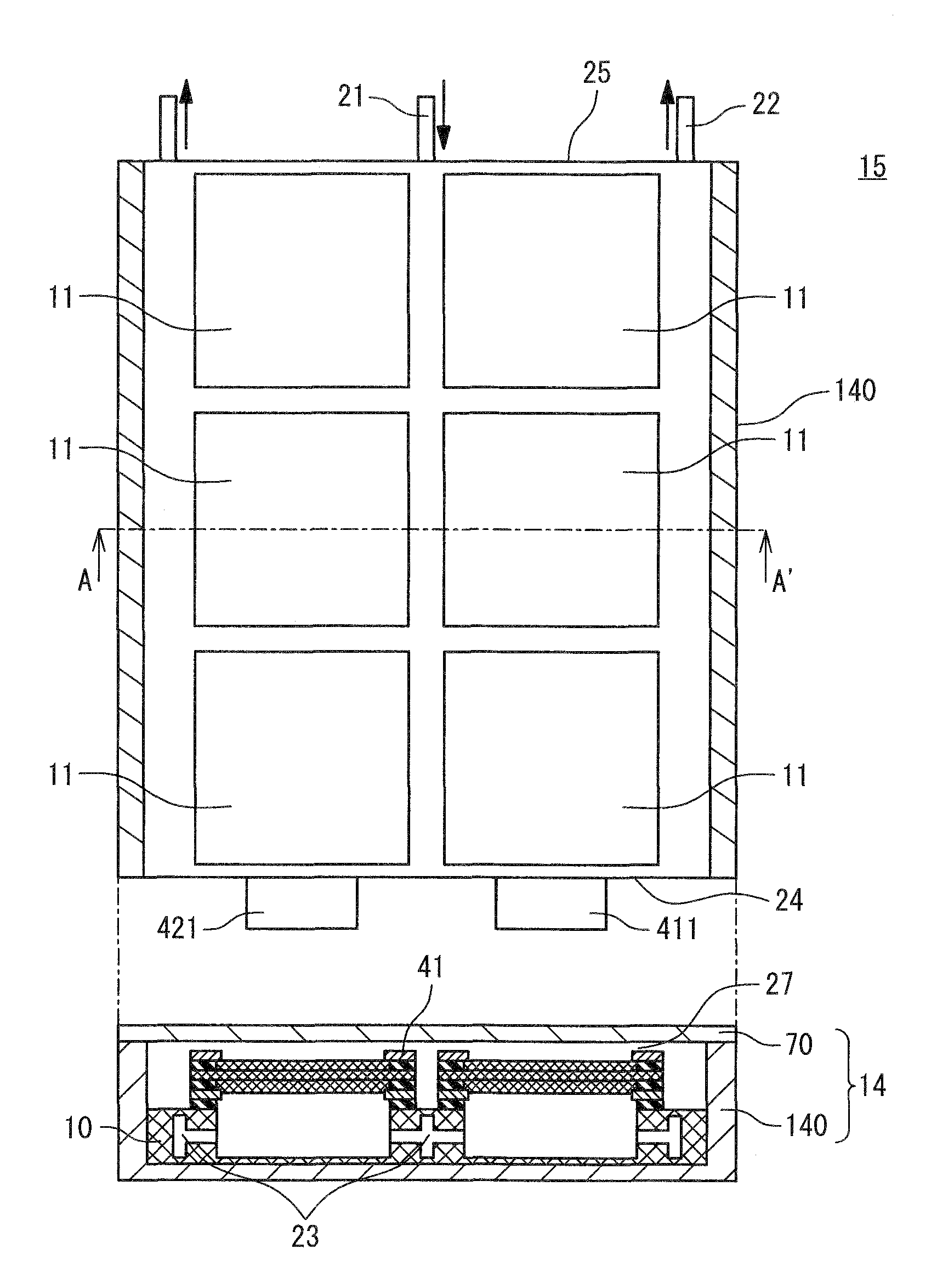
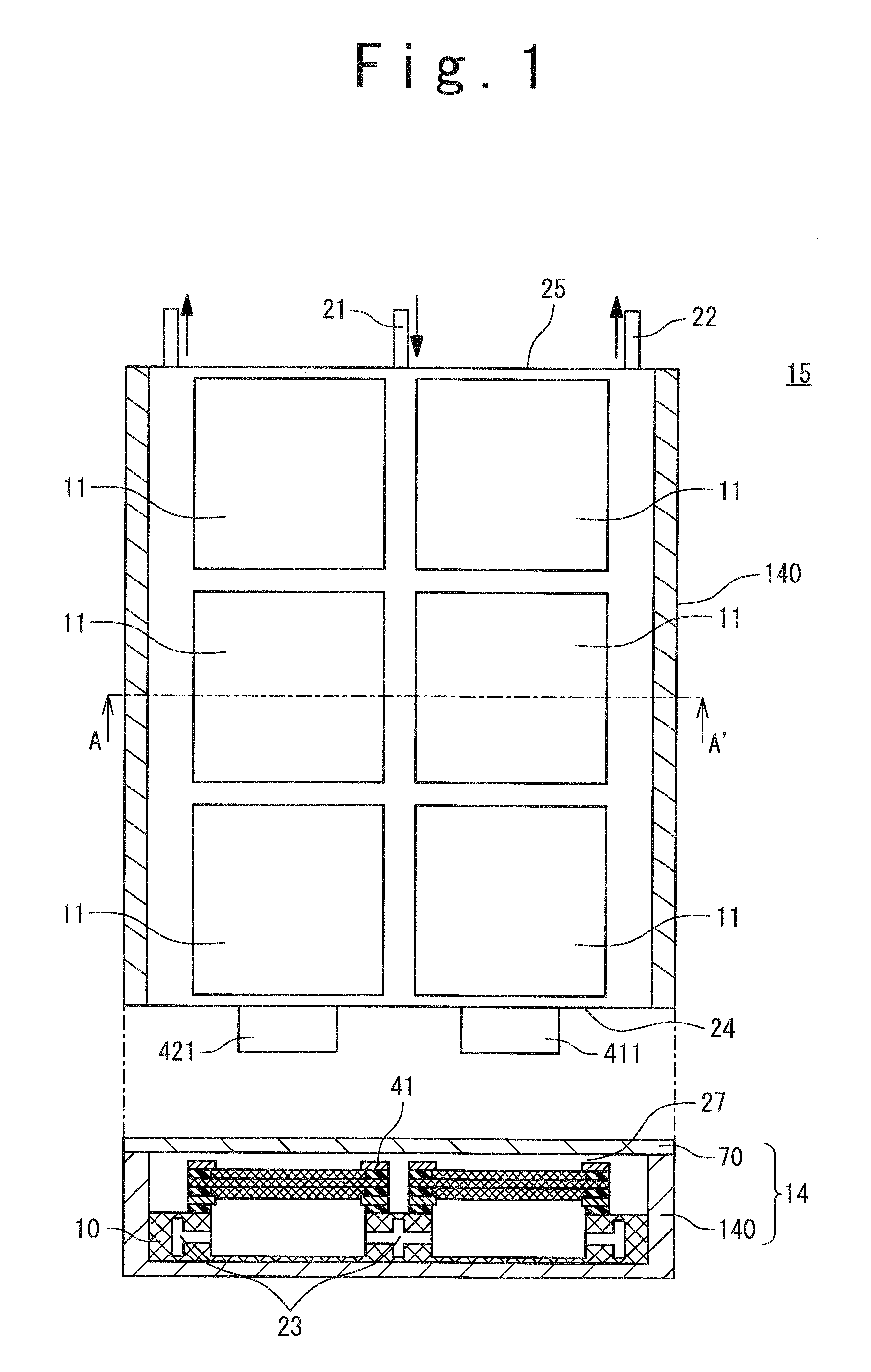
[0112]A structure of a fuel cell used in a first example will be explained below. In the present example, the fuel cell system 1 shown in FIG. 2 is manufactured.

[0113]At first, catalyst-supporting carbon fine particles which supports platinum fine particles with a particle diameter within a range from 3 to 5 nm at 50% ratio by weight on carbon particles (the KETJENBLACK EC600JD manufactured by LION Co.) was prepared. By adding 5% by weight of Nafion solution (name of commodity; DE521, the “Nafion” is a registered trade mark of Dupont Co.) into 1 g of the catalyst-supporting carbon fine particles and agitating the solution, catalyst paste for forming the cathode was obtained. By coating the catalyst paste on carbon paper (TGP-H-120 manufactured by Toray Co.) as a substrate at a coating amount from 1 to 8 mg / cm2 and drying it, the cathode 31 of 4 cm×4 cm was manufactured. Meanwhile, a catalyst paste for forming an anode was obtained under a same condition as that in obtaining the cata...

second example

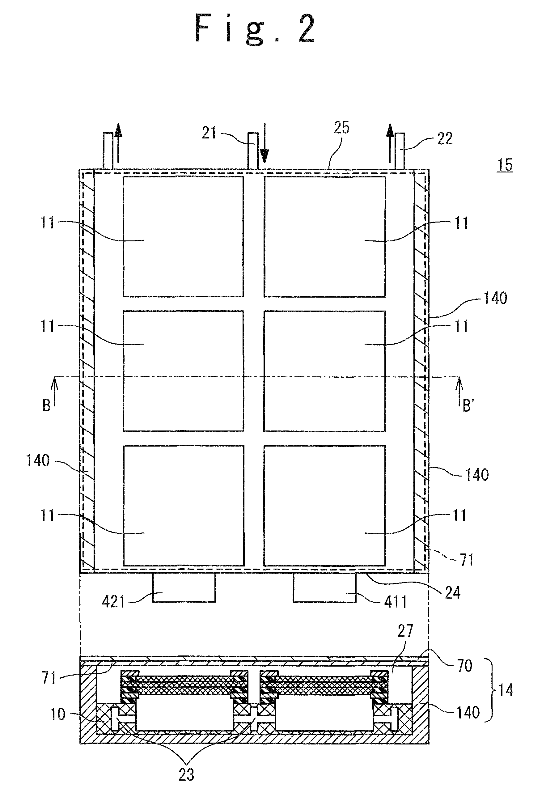
[0121]A structure of a unit fuel cell used in a second example will be explained below. A manufacturing method and a structure of the MEA are the same as those of the first example, and a structure of the fuel cell stack 15 is also the same as that of the first example. Other conditions are also the same if not other mentioned below.

[0122]As for the second example, the fuel cell system 1 shown in FIG. 3 was manufactured. That is, only arrangement of the mesh 71 in the first example was changed. A size of the mesh 71 is 20 cm long side×14.5 cm short side so that the mesh 71 cannot be sandwiched between the partitions provided on both sides of the chassis body 140 and the lid 70.

third example

[0123]A structure of a unit fuel cell used in a third example will be explained below. A manufacturing method and a structure of the MEA are the same as those of the first example, and a structure of the fuel cell stack 15 is also the same as that of the first example. Other conditions are also the same if not other mentioned below.

[0124]As for the third example, the fuel cell system shown in FIG. 4 was manufactured. That is, the shape of the mesh in the first example was changed. A size of the mesh is 20 cm long side×14.5 cm short side so that the mesh 71 cannot be sandwiched between the partitions provided on both sides of the chassis body 140 and the lid 70. Furthermore, in a clearance between the unit fuel cells 11 forming two rows, the mesh 71 is divided with keeping a clearance of 0.5 cm.


PUM

PropertyMeasurementUnit
thicknessaaaaaaaaaa
sizeaaaaaaaaaa
sizeaaaaaaaaaa

Abstract

A fuel cell system includes: a fuel cell stack configured to have a plurality of unit fuel cells arranged on an identical plane; a chassis configured to cover at least one side of said fuel cell stack via an air flow space; and a condensation water holding member configured to be provided in at least a part between said fuel cell stack and said chassis, have a mesh shape and have a function for keeping moisture.

Description

TECHNICAL FIELD[0001]The present invention relates to a fuel cell system and especially relates to a planar stack type fuel cell system in which a plurality of fuel cells is arranged in plane.BACKGROUND ART[0002]A polymer electrolyte fuel cell system includes a Membrane and Electrode Assembly (hereinafter referred to as MEA) structured by holding and sandwiching a solid polymer electrolyte membrane between an anode and a cathode. A fuel cell in which liquid fuel is directly supplied for the anode is referred to as a direct fuel cell. When the fuel cell generates electricity, the fuel is supplied to the anode at first. The supplied fuel is decomposed on catalysts supported on the anode and generates protons, electrons, and intermediate products. Generated cations move to the cathode side after passing through the solid polymer electrolyte membrane and generated electrons move to the cathode side through an external load. Electricity is generated by a reaction where the protons and el...

Claims


Application Information

Patent Timeline
Patent Type & Authority Patents(United States)
IPC IPC(8): H01M8/02H01M8/10
CPCH01M8/04119H01M8/04171H01M8/1097H01M8/2455H01M2250/30Y02B90/18Y02E60/521Y02B90/10Y02E60/50
Inventor SEKINO, SHOJIMANAKO, TAKASHINISHI, TAKANORI
Owner NEC CORP
Why Eureka
Try Eureka