Method and system for performing distributed outer loop power control in wireless communication networks

a wireless communication network and distributed outer loop technology, applied in power management, electrical equipment, radio transmission, etc., can solve the problems of low sinr limit of maximum data rate, no systematic technique currently available, etc., and achieve the effect of increasing sinr

Inactive Publication Date: 2009-04-09
HONEYWELL INT INC
View PDF52 Cites 215 Cited by
  • Summary
  • Abstract
  • Description
  • Claims
  • Application Information

AI Technical Summary

Benefits of technology

[0008]In a first example embodiment, a method for performing distributed outer loop power control in a wireless communication network is provided. The method includes the steps of determining a transmit power for a plurality of transmitting nodes such that signals sent from each of the transmitting nodes are received at a receiver associated with a receiving node at a predetermined signal-to-interference plus noise ratio (SINR) set point, increasing the SINR at the receiving node of one or more transmitting nodes of the plurality of transmitting nodes if a saturation value for a front end of the receiver associated with the receiving node is not near a predetermined saturation value, and decreasing the SINR at the receiving node of the one or more transmitting nodes of the plurality of transmitting nodes if the saturation value for the front end of the receiver associated with the receiving node is near the predetermined saturation value.
[0009]In a second example embodiment, a method for performing distributed outer loop power control in a cellular communication network is provided. The method includes the steps of determining a transmit power for a plurality of mobile units such that signals sent from each of the mobile units are received at a receiver associated with a base station at a predetermined signal-to-interference plus noise ratio (SINR) set point, increasing the SINR at the base station receiver of one or more of the mobile units if a saturation value for a front end of the base station receiver is not near a predetermined value, and decreasing the SINR at the base station receiver if the saturation value for the front end of the base station receiver is near the predetermined saturation value.
[0010]In a third example embodiment, a wireless communication system is provided. The system includes a plurality of nodes including at least one receiving node and a plurality of transmitting nodes, each transmitting node of the plurality of transmitting nodes communicatively coupled to the at least one receiving node. The at least one receiving node is configured to receive a signal transmitted by at least one transmitting node of the plurality of transmitting nodes, and the at least one transmitting node of the plurality of transmitting nodes is configured to determine a transmit power such that signals sent from the at least one transmitting node is received at the at least one receiving node at a predetermined SINR set point (e.g., using power control algorithm disclosed in U.S. patent application Ser. No. 11 / 269,383), increase an SINR at the at least one receiving node if a saturation value for a front end of a receiver associated with the at least one receiving node is not near a predetermined saturation value, and decrease the SINR at the at least one receiving node if the saturation value for the front end of the receiver associated with the at least one receiving node is near the predetermined saturation value.

Problems solved by technology

A relatively low SINR limits the maximum data rate, because data received with a low signal-to-noise ratio requires a large amount of processing to extract the transmitted signal from the received waveform.
However, a significant problem with the existing power control techniques is that there is no systematic technique currently available that can exploit the advantages of today's wireless radio transceivers that have different receive antenna saturation levels, different transmit power limits, and / or are capable of adjusting to wide variations in traffic (e.g., in military wireless networks).

Method used


Image

  • Method and system for performing distributed outer loop power control in wireless communication networks
  • Method and system for performing distributed outer loop power control in wireless communication networks
  • Method and system for performing distributed outer loop power control in wireless communication networks

Examples


Embodiment Construction

)

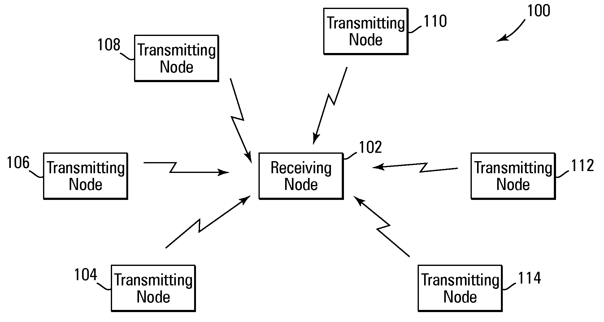
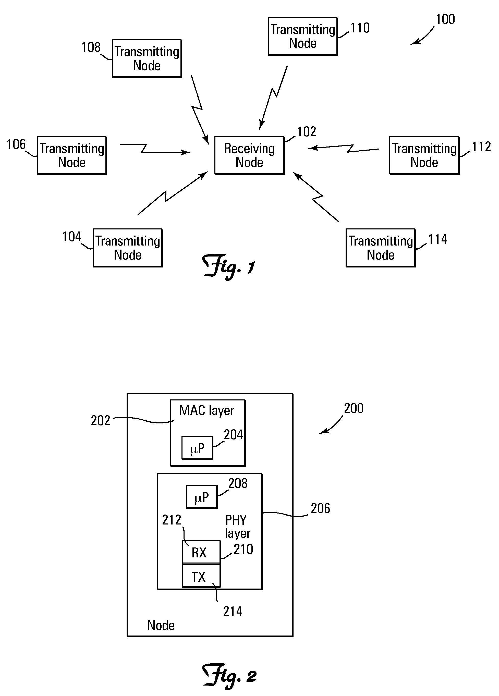
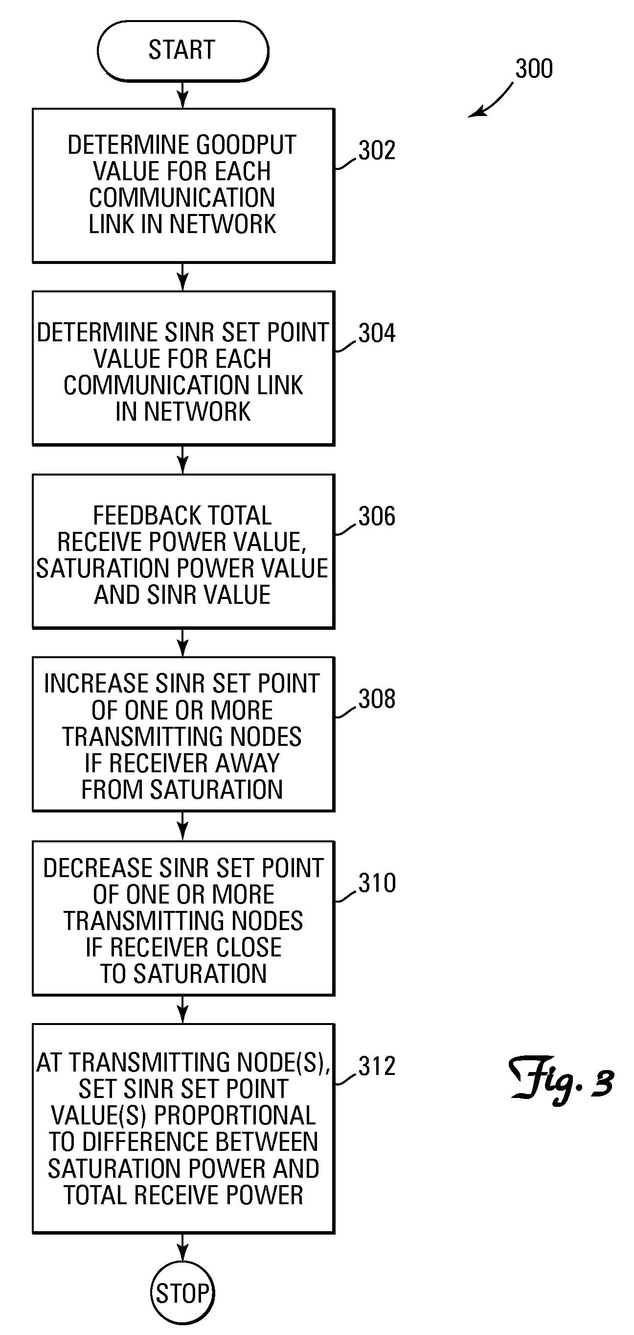
[0015]The present invention provides a method and system for performing distributed outer loop power control in wireless communication networks. Essentially, the present invention provides a distributed outer loop power control technique that resolves problems related primarily, but not exclusively, to receive signal saturation. For example, in certain wireless networks, each radio transceiver has a certain received signal level at which its front end (e.g., antennas, filters, etc.) becomes saturated. Consequently, it would be advantageous to impose a constraint on the existing wireless network power control techniques in order to avoid this saturation level. In this regard, the present invention provides a method and system for performing distributed outer loop power control that can be used to reduce frame error set points or SINR set points in a wireless communication network if there is an increase in the overall level of the signals received at a receiver, and / or uniformly or ...


PUM


Abstract

A method and system for performing distributed outer loop power control in a wireless communication network are disclosed. The method includes the steps of determining a transmit power for a plurality of transmitting nodes such that signals sent from each of the transmitting nodes are received at a receiver associated with a receiving node at a predetermined signal-to-interference plus noise ratio (SINR) set point, increasing the SINR at the receiving node of one or more transmitting nodes of the plurality of transmitting nodes if a saturation value for a front end of the receiver associated with the receiving node is not near a predetermined saturation value, and decreasing the SINR at the receiving node of the one or more transmitting nodes of the plurality of transmitting nodes if the saturation value for the front end of the receiver associated with the receiving node is near the predetermined saturation value.

Description

RELATED APPLICATIONS[0001]The present application is related to commonly assigned and co-pending U.S. patent application Ser. No. 11 / 269,383 entitled “SYSTEM AND METHOD TO PERFORM STABLE DISTRIBUTED POWER CONTROL IN A WIRELESS NETWORK”, filed on Nov. 8, 2005, and U.S. patent application Ser. No. 11 / 841,364 entitled “METHOD FOR ADJUSTING POWER AT A NODE”, filed on Aug. 20, 2007, each of which is incorporated herein by reference in its entirety.FIELD OF THE INVENTION[0002]The invention is related to the telecommunications field, and more particularly, but not exclusively, to a method and system for performing distributed outer loop power control in wireless communication networks.BACKGROUND OF THE INVENTION[0003]In many existing wireless communication systems, such as for example, certain cellular communication systems, the transmit power levels from the mobile units to the base station of the systems are controlled. For example, in some multiple-access systems utilizing spread spectr...

Claims


Application Information

Patent Timeline
Patent Type & Authority Applications(United States)
IPC IPC(8): H04Q7/20
CPCH04W52/12H04W52/40H04W52/241
Inventor ARIYUR, KARTIK B.
Owner HONEYWELL INT INC
Why Eureka
Try Eureka