

Cardiovascular ultrasound probe and ultrasound image system
- Summary
- Abstract
- Description
- Claims
- Application Information
AI Technical Summary
Problems solved by technology
Method used
Image

Examples
first embodiment
[0042]A cardiovascular ultrasound probe (hereinafter simply called a “probe”) and an ultrasound image system according to the present invention are explained as follows with reference to FIGS. 1 to 10.
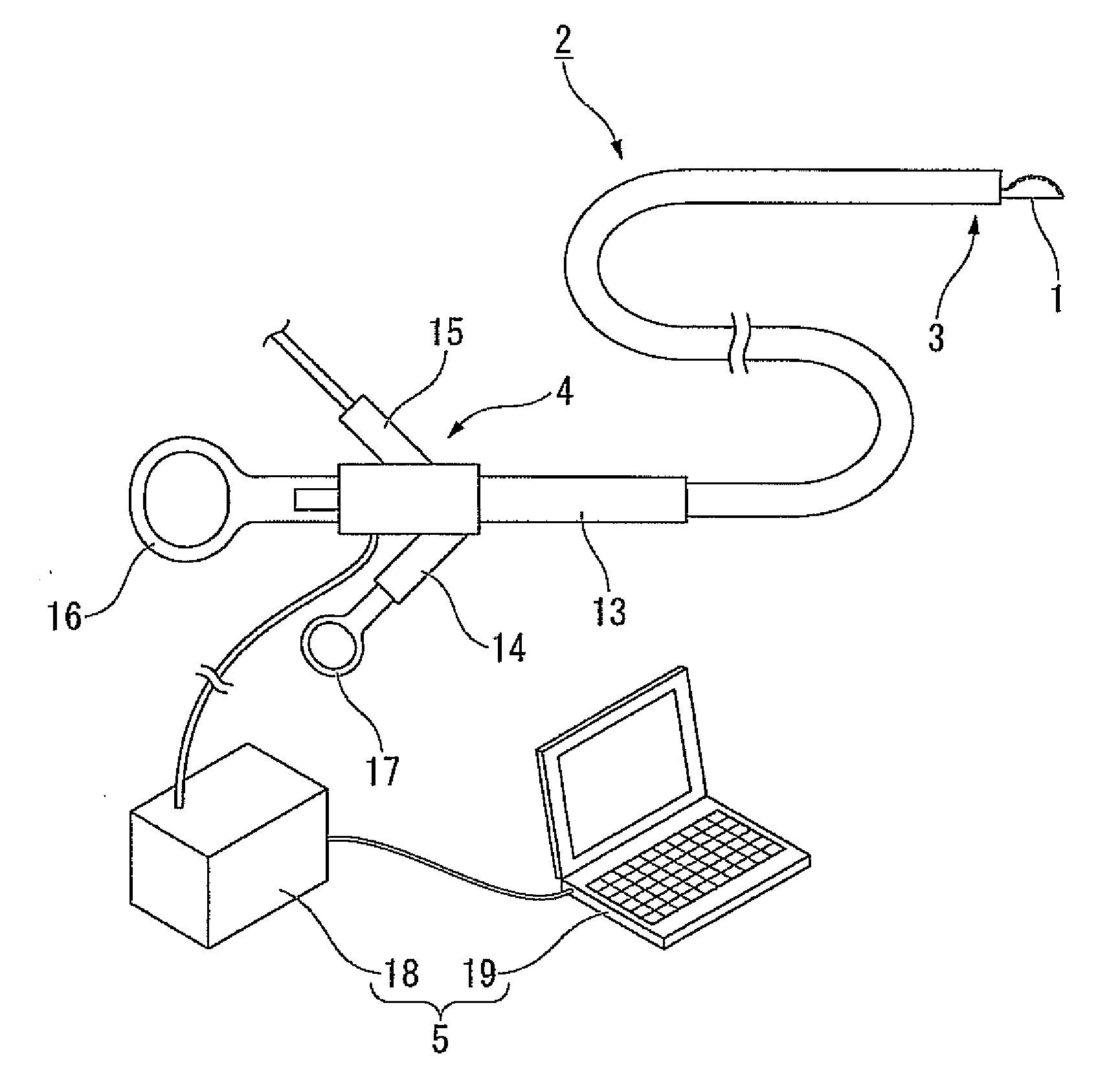
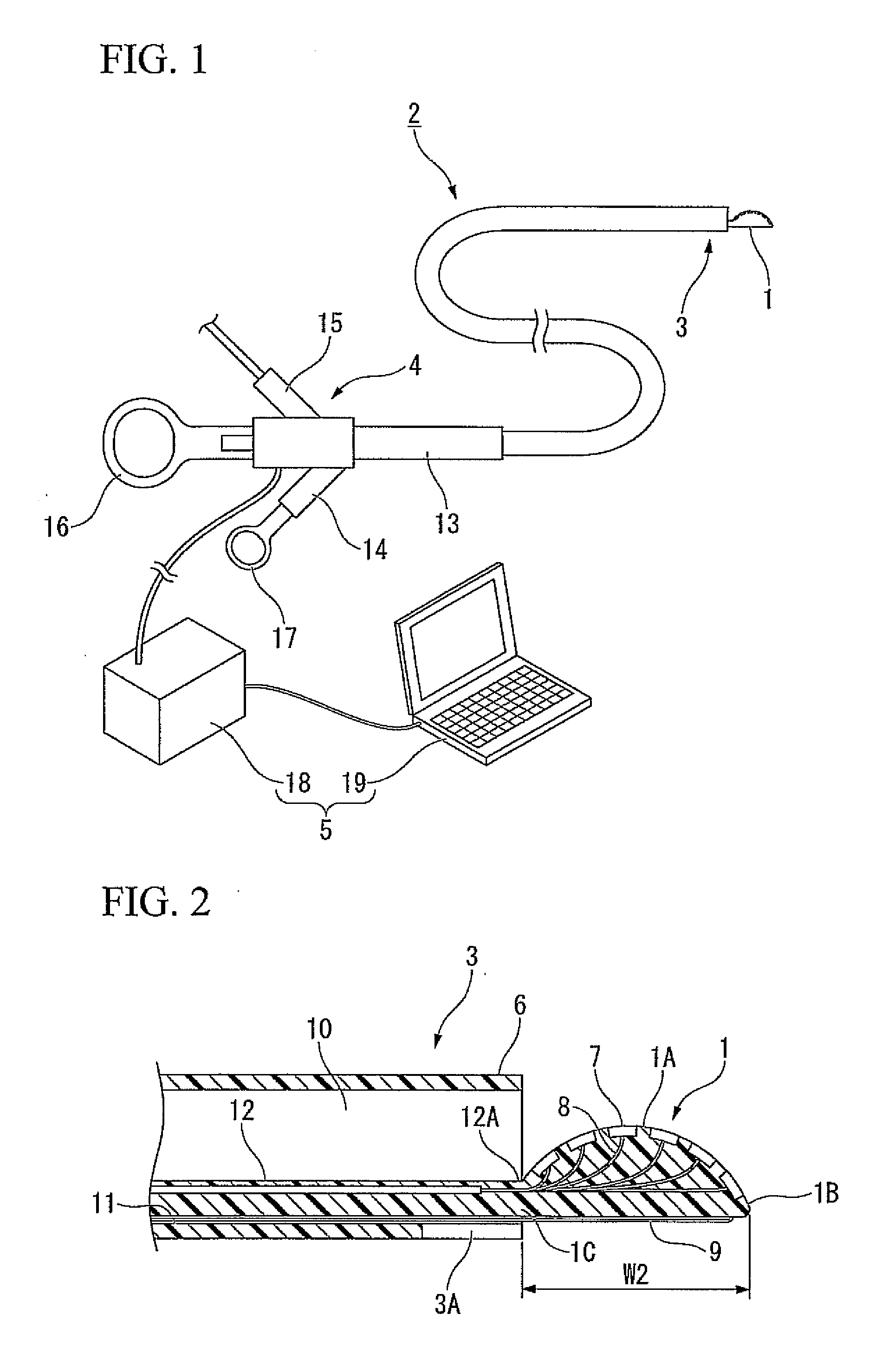
[0043]FIG. 1 is a schematic view of an ultrasound image system 2 provided with a probe 1 according to the present embodiment. The ultrasound image system 2 is provided with: a tip section 3 having the probe 1 thereon; a maneuvering section 4 provided to the proximal end of the probe 1; and an image-processing section 5 that conducts image-processing and image-display with respect to a signal obtained by the probe 1.
[0044]FIG. 2 is an enlarged view showing a part of a tip section 3 in cross-section. The tip section 3 is provided with the probe 1 and a sheath 6 having the probe 1 at a distal end thereof.
[0045]The probe 1, which is made of an elastic material, e.g., resin, has a convex surface 1A for transmitting and receiving ultrasound waves. A plurality of ultrasound transducers 7 (her...
second embodiment
[0074]the present invention will be explained next with reference to FIGS. 11 to 19. An ultrasound image system 21 according to the present embodiment is different from the above-explained ultrasound image system 2 due to the different connection between a probe and a sheath and due to a balloon attached to the sheath.
[0075]Note that elements that are equivalent to the ultrasound image system 2 according to the first embodiment will be assigned the same reference symbols and redundant explanations thereof will be omitted in each of the following embodiments.
[0076]FIG. 1 is an enlarged view showing a part of a tip section 22 of the ultrasound image system 21 in cross-section. An end section 1C of a probe 1 that is identical to that of the first embodiment is connected to a sheath 24 via a hinge 23.
[0077]A balloon 25 made of a resin, e.g., polyethylene terephthalate (PET) or a rubber is provided to an outer periphery in the vicinity of the distal end of the sheath 24. An inflation tub...
third embodiment
[0090]the present invention will be explained next with reference to FIGS. 20 to 27. An ultrasound image system 31 according to the present embodiment is different from the above-explained ultrasound image system 2 with respect to the structure of a probe.
[0091]Note that elements that are equivalent to the ultrasound image system 2 according to the first embodiment will be assigned the same reference symbols and redundant explanations thereof will be omitted in each of the following embodiments.
[0092]FIG. 20 is an enlarged view showing a part of a tip section 32 of the ultrasound image system 31 in cross-section. A substantially bar-shaped probe 33 made of a flexible material has a transmitting-and-receiving surface 33A having transducers 7 similar to those of the first embodiment disposed at a constant pitch. A plurality of identical grooves 34, having a substantial V-letter-shaped cross section, is formed on the transmitting-and-receiving surface 33A and on the opposite deformable...
PUM
 Abstract
Description
Claims
Application Information