Catheter device

a catheter and catheter technology, applied in the field of catheters, can solve the problems of transfemoral implantation, inability to reverse heart failure, limited haemodynamic improvement, etc., and achieve the effect of further optimising the pump performan

Active Publication Date: 2009-04-09
AIS AACHEN INNOVATIVE SOLUTIONS
View PDF28 Cites 290 Cited by
  • Summary
  • Abstract
  • Description
  • Claims
  • Application Information

AI Technical Summary

Benefits of technology

[0016]Due to the frame structure of the rotor with its boundary frame and rotor struts, the rotor is very stable but still capable of folding and of being compressed to a diameter virtually as small as may be desired. Due to the fact that, in principle, the rotor may be virtually as long as desired in the axial and radial directions, it may be optimised for maximum pump performance, depending on the space available. It is therefore possible to optimise pump performance for each application.
[0017]The rotor is so compressible that it may be introduced into the body, using a puncture needle, through a puncture with a diameter of approximately 9 french (approx. 3 mm). The automatic unfolding of the rotor makes possible a rotor diameter which is many times greater than the diameter of the rotor in the compressed state. By this means a high pump performance is obtained.
[0018]Through the scaffolding-like structure of the boundary frame and rotor struts, the rotor has great strength, enabling it to operate at high speeds without becoming unbalanced. A prototype of this catheter device was operated over several hours to pump a fluid at a speed of around 32,000 rpm. The rotor has a diameter of around 18 french (ca. 6 mm) and was designed so as to obtain a pressure difference of approximately 120 mmHg. This is an exceptional performance for such a miniaturised pump. A distinct advance in reliability and operating life was also achieved by this catheter device.
[0021]Expediently the rotor is surrounded by a tubular pump section of a pump housing. The pump housing is formed by a mesh, the openings of which are closed by an elastic covering, at least in the area of the pump section. Such a pump housing may be made with a small clearance gap from the rotor, resulting in optimal flow conditions and the chance for further optimisation of pump performance.
[0022]The mesh of the pump housing is preferably made of a memory material which can be compressed together with the rotor. The pump housing protects the rotor from external influences.

Problems solved by technology

The reduced coronary supply can lead to irreversible heart failure.
The obtainable haemodynamic improvement is however very limited since, on account of the construction principle of the IABP, no active blood delivery takes place.
The disadvantage of the system is that the transfemoral implantation, due to the large diameter of the rotor, is possible only through an operation involving a femoral arteriotomy and if necessary by a graft coupling.
This reduces the rotor speed and therefore the mechanical stress on the components.

Method used


Image

  • Catheter device
  • Catheter device
  • Catheter device

Examples


Embodiment Construction

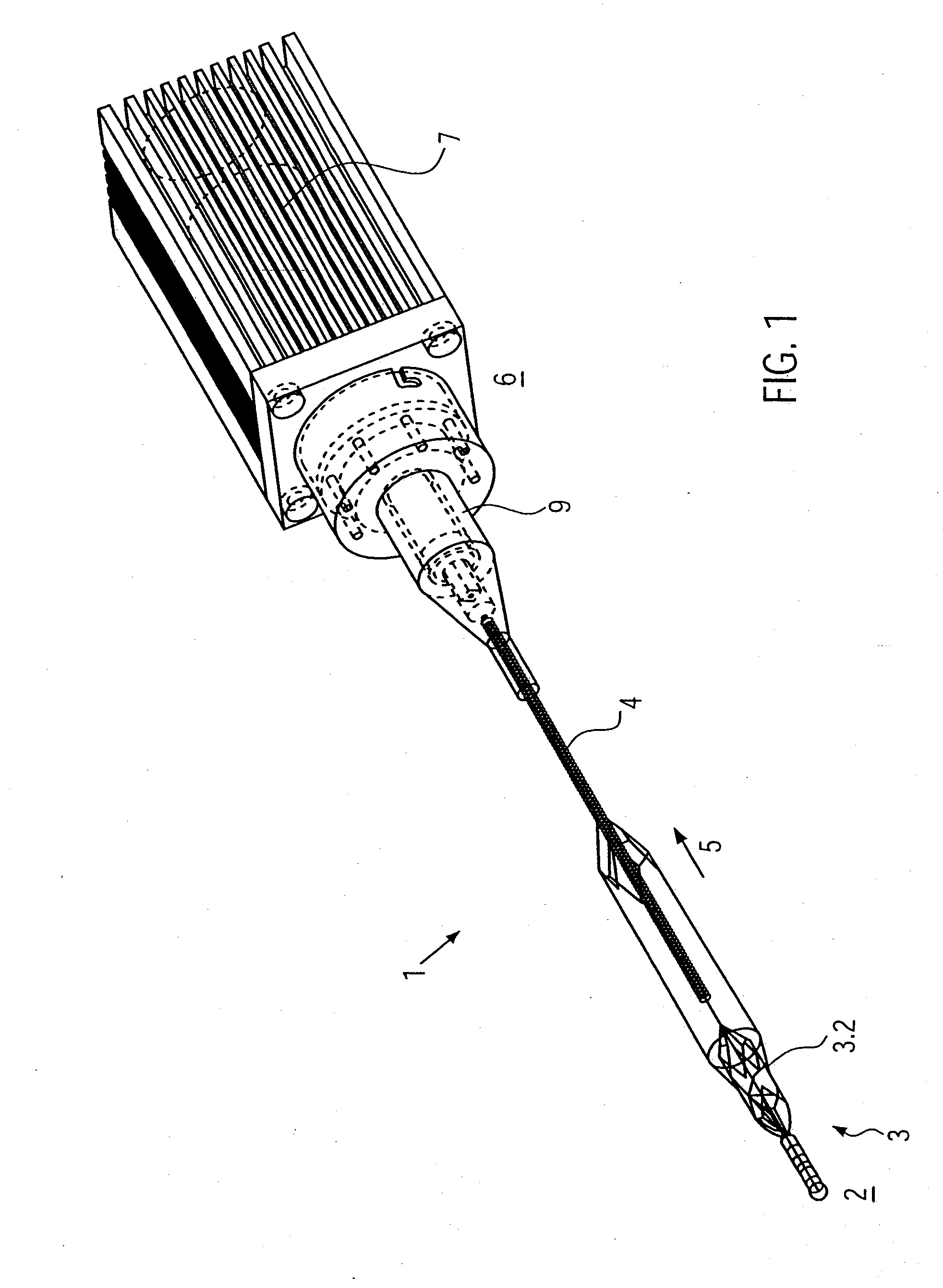
[0051]FIG. 1 shows a catheter device 1. The catheter device 1 according to the invention represents a pump. The catheter device 1 has a pump head 3 at a distal end 2.

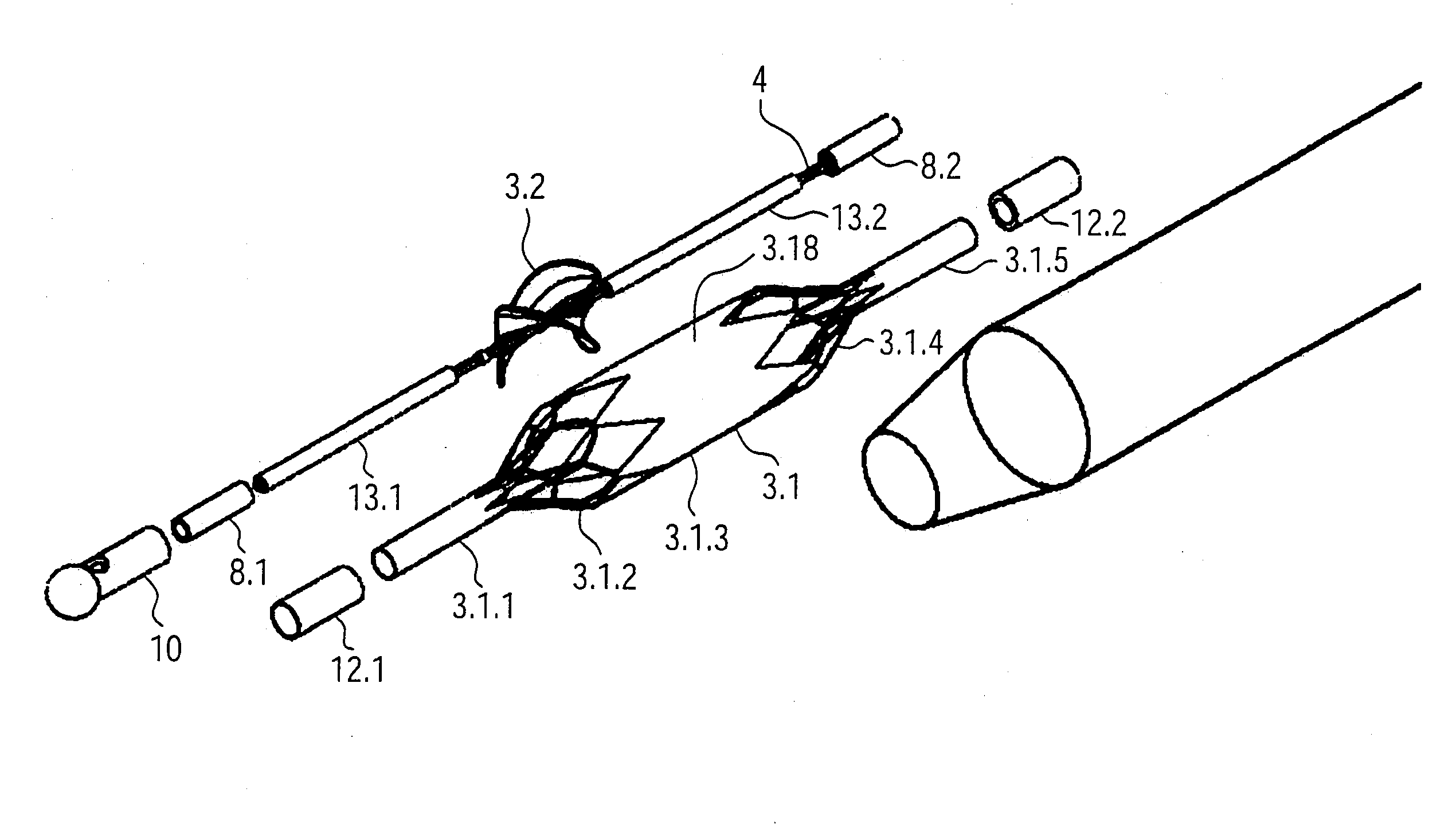
[0052]The pump head 3 has a rotor 3.2, for pumping a medium in the flow direction 5, which is connected to a drive shaft 4. The flow direction 5 is from the distal end 2 to a proximal end 6. Located at the proximal end 6 away from the pump head 3 is a motor 7. The drive shaft 4 is encompassed by a catheter body 8 and connected non-positively by means of a clutch 9 to the motor 7.

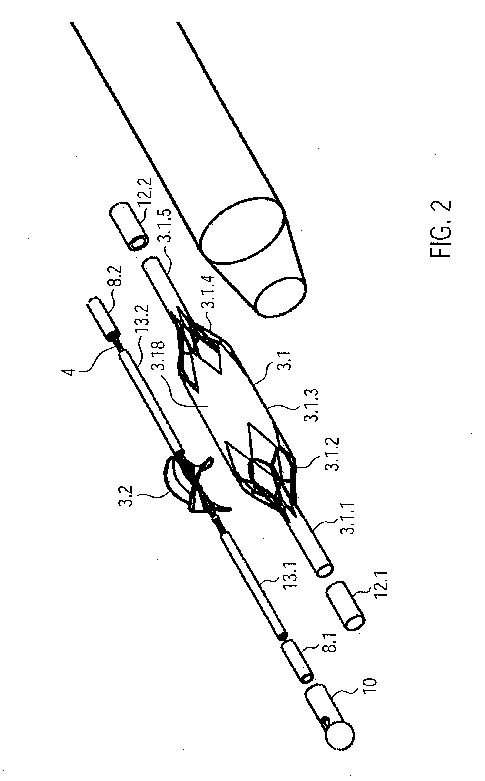
[0053]First of all the pump head 3 will be explained in more detail below. The pump head 3 comprises a body cap 10 at the distal end, the rotor 3.2 mounted on the drive shaft 4, a pump housing 3.1 and an outlet hose 18.

[0054]The body cap 10 is formed by a ball 10.1 with an attached cylindrical section 10.2. The body cap 10 is made for example of stainless steel (FIG. 2, FIG. 3). The body cap 10 could be made of polyethylene PE, polypropylene PP,...


PUM


Abstract

The catheter device comprises a drive shaft connected to a motor, and a rotor mounted on the drive shaft at the distal end section. The rotor has a frame structure which is formed by a screw-like boundary frame and rotor struts extending radially inwards from the boundary frame. The rotor struts are fastened to the drive shaft by their ends opposite the boundary frame. Between the boundary frame and the drive shaft extends an elastic covering. The frame structure is made of an elastic material such that, after forced compression, the rotor unfolds automatically.

Description

CROSS-REFERENCE TO RELATED APPLICATIONS[0001]This application claims priority to U.S. Provisional Application No. 60 / 978,249 filed in the United States Patent and Trademark Office on Oct. 8, 2007, the contents of which are hereby incorporated by reference herein for all purposes.BACKGROUND OF THE INVENTION[0002]1. Field of the Invention[0003]The invention relates to a catheter device which is a miniaturised pump.[0004]2. Related Art[0005]Implantable blood pumps are used increasingly in the treatment of patients with serous heart conditions. Such blood pumps have so far been provided mainly for long-term use. However, blood pumps are also being developed which are designed for short-term support for the heart and may be inserted by minimally invasive means. Here the medical objectives are stress-relief for and recovery of the heart, or to provide bridging until a possible heart transplant. The range of application of such pumps depends on the one hand on the simplicity of inserting t...

Claims


Application Information

Patent Timeline
Patent Type & Authority Applications(United States)
IPC IPC(8): A61M25/04A61M1/12A61M1/00A61M29/00A61M60/13A61M60/253A61M60/422
CPCA61M1/12F04D3/02A61M25/0069A61M25/0082A61M1/1046A61M1/101A61M1/1024A61M1/122A61M1/125A61M1/1031F04D29/242A61M1/1034F04D29/42F04D29/247A61M1/1012A61M25/0074Y10S415/90F04D3/005F04D29/181A61M25/0068A61M60/414A61M60/148A61M60/422A61M60/13A61M60/253
Inventor PFEFFER, JOACHIM GEORGSCHMITZ-RODE, THOMASGUNTHER, ROLF W.
Owner AIS AACHEN INNOVATIVE SOLUTIONS
Why Eureka
Try Eureka