Exhaust particulate matter measuring apparatus

a technology of particulate matter and measuring apparatus, which is applied in the direction of exhaust treatment electric control, electrical control, instruments, etc., can solve the problems of inability to accurately combust the soot particles settled on the molded member, and inability to measure the amount of soot with high accuracy, and achieve the effect of accurate measuremen

Inactive Publication Date: 2009-04-16
TOYOTA JIDOSHA KK
View PDF7 Cites 36 Cited by
  • Summary
  • Abstract
  • Description
  • Claims
  • Application Information

AI Technical Summary

Benefits of technology

[0008]The present invention provides an exhaust particulate matter measuring apparatus that accurately measures that amount of particulate matter present in exhaust gas.

Problems solved by technology

For this reason, the problem arises that, when there is not a sufficient amount of oxygen in the area surrounding the soot sensor, even if the molded member is heated by the electrical heating member, it is not possible to properly combust the soot particles settled on the molded member, making it impossible to measure the soot amount with high accuracy.

Method used


Image

  • Exhaust particulate matter measuring apparatus
  • Exhaust particulate matter measuring apparatus
  • Exhaust particulate matter measuring apparatus

Examples


first embodiment

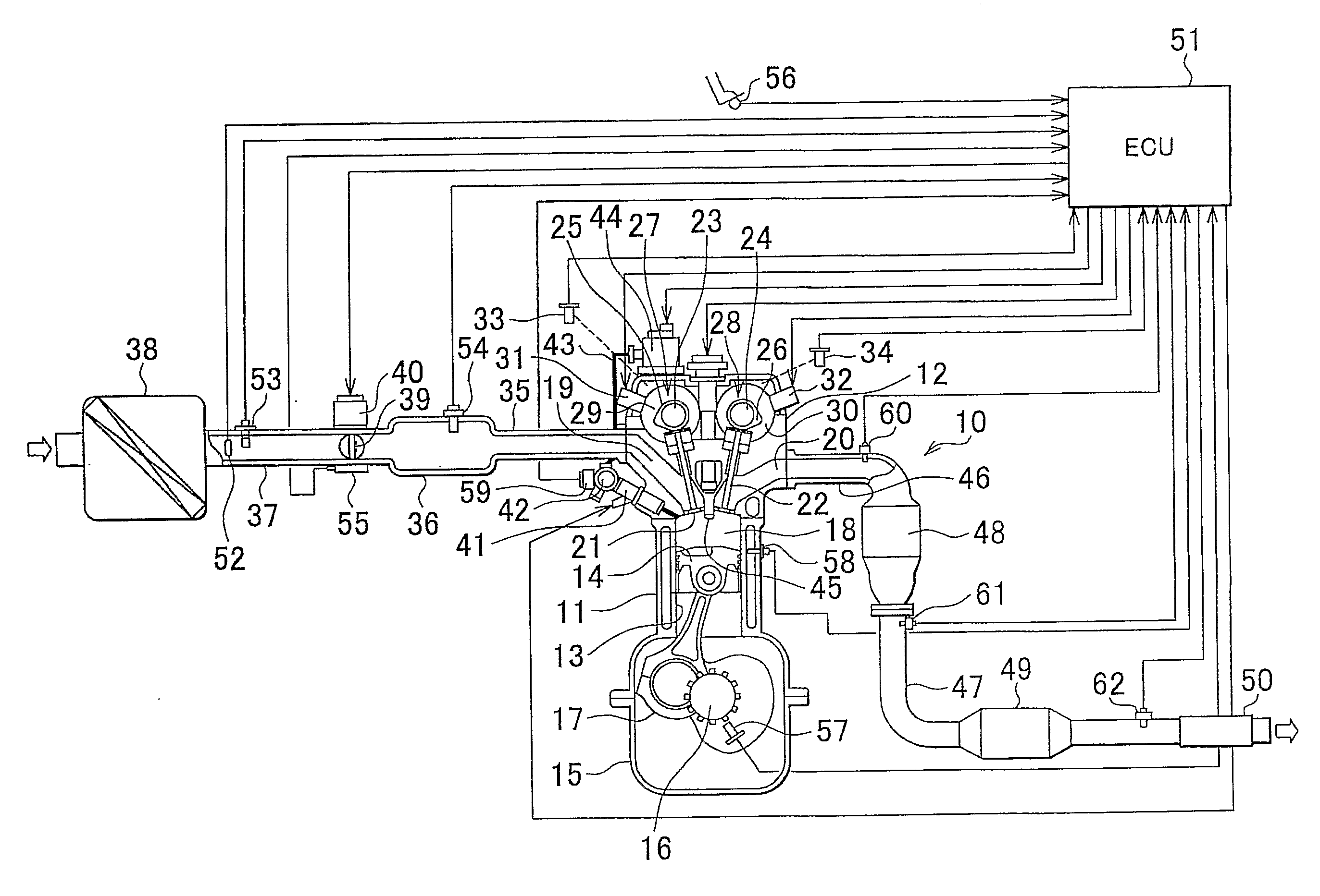
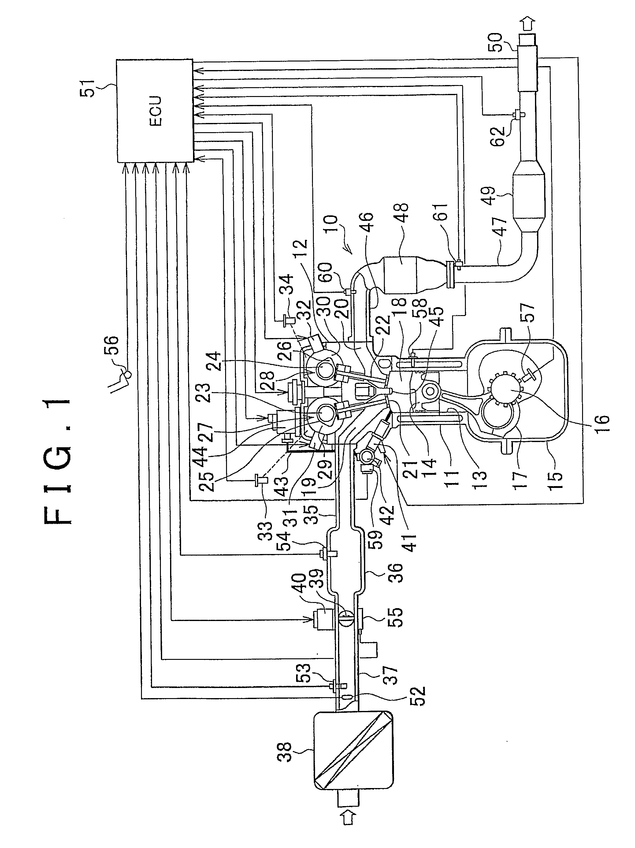
[0033]In an internal combustion engine to which the exhaust particulate matter measuring apparatus of the first embodiment is applied, as shown in FIG. 1, the engine 10 may be a four-cylinder direct-injection type engine, in which a cylinder head 12 is fitted tightly onto a cylinder block 11, wherein a pistons 14 are fitted into a plurality of cylinder bores 13 formed in the cylinder block 11 to enable up-and-down movement within the cylinder block 11. A crankcase 15 is fitted tightly to the bottom of the cylinder block 11. A crankshaft 16 is rotatably supported inside the crankcase 15, and each of the pistons 14 is linked to the crankshaft 16 via a connecting rod 17. In FIG. 1, only one cylinder and cylinder bore of four cylinders is shown.

[0034]A combustion chamber 18 is formed by the wall surface of the cylinder bore 13 of the cylinder block 11, the lower surface of the cylinder head 12, and the upper surface of the piston 14. This combustion chamber 18 is a pent-roof shaped, in ...

second embodiment

[0067]The method of measuring the exhaust particulate matter with the exhaust particulate matter measuring apparatus is described in detail below, with reference being made to the flowchart of FIG. 8.

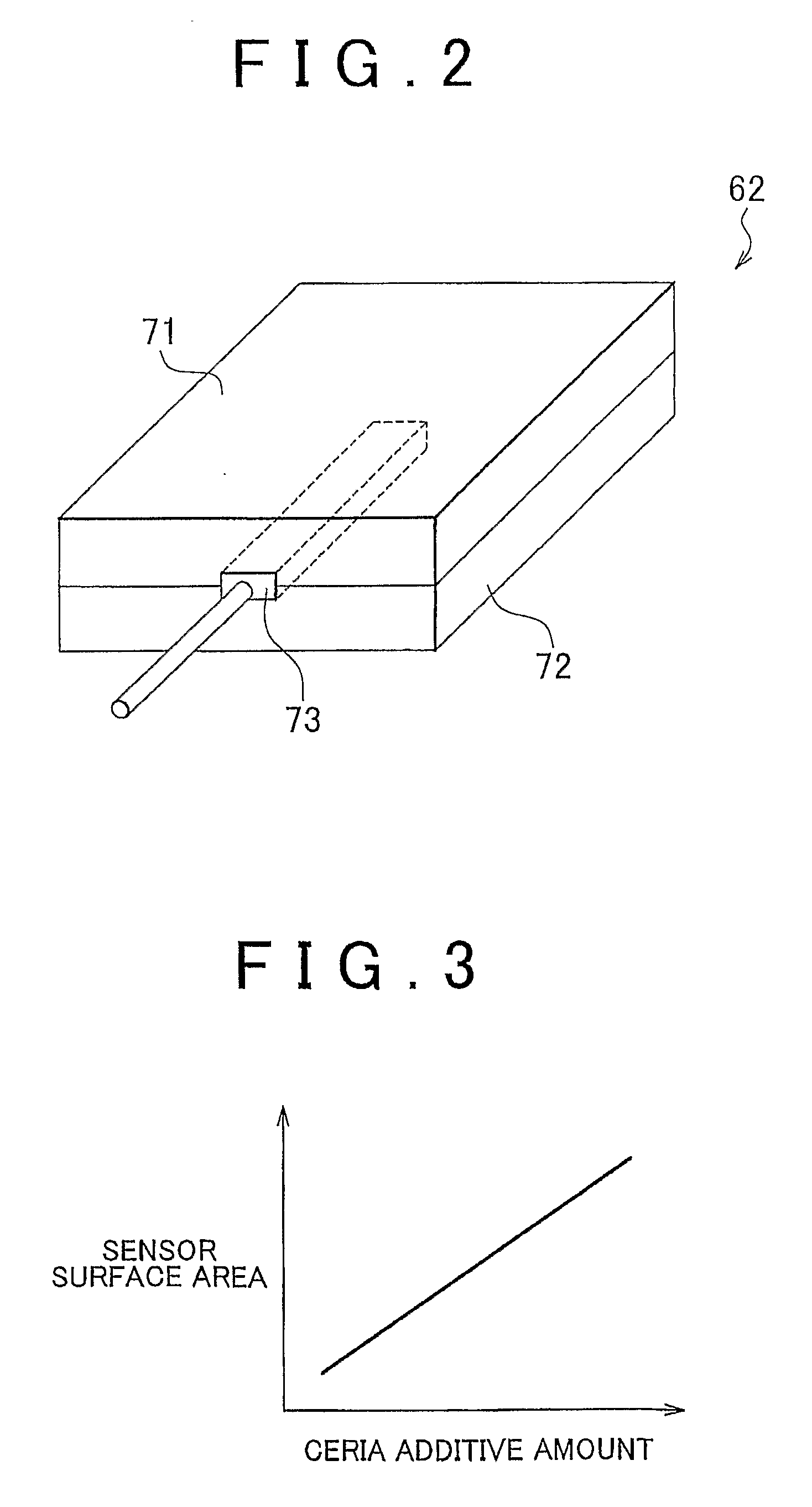
[0068]At step S31, a determination is made of whether the engine 10 is completed warmed-up, that is, whether the engine coolant temperature detected by the coolant temperature sensor 58 is at least a prescribed engine warm-up coolant temperature. At this point, if the determination is made that the engine coolant temperature has reached the engine warm-up coolant temperature, at step S32, the electrical heater 72 in the PM sensor 62 is electrically powered to heat the oxidation catalyst 71, thereby combusting the exhaust particulate matter settled in the oxidation catalyst 71. Then, at step S33, a determination is made of whether the exhaust particulate matter settled in the oxidation catalyst 71 of the PM sensor 62 has been completely combusted, based on the temperature change of the ...

third embodiment

[0081]The method of measuring the exhaust particulate matter with the exhaust particulate matter measuring apparatus is described in detail below, with reference being made to the flowchart of FIGS. 9A and 9B.

[0082]At step S51, a determination is made of whether the engine 10 is completed warned-up, that is, whether the engine coolant temperature detected by the coolant temperature sensor 58 is at least a prescribed engine warm-up coolant temperature. At this point, if the engine coolant temperature has reached the engine warm-up coolant temperature, at step S52, the electrical heater 72 in the PM sensor 62 is electrically powered to heat the oxidation catalyst 71, thereby combusting the exhaust particulate matter settled in the oxidation catalyst 71. Then, at step S53, a determination is made of whether the exhaust particulate matter settled in the oxidation catalyst 71 of the PM sensor 62 has been completely combusted, based on the temperature change in the oxidation catalyst 71....


PUM


Abstract

A PM sensor for measuring particle matter in exhaust gas is disposed between a three-way catalyst and a muffler in an exhaust pipe, and has an oxidation catalyst and an electrical heater that are stacked together, and a temperature sensor that measures a temperature of the oxidation catalyst interposed between the oxidation catalyst and the electrical heater. The oxidation catalyst carries a ceria as an oxygen-storing agent that occludes oxygen in the exhaust gas, and a ECU calculates a sediment amount of the exhaust particulate matter based on an amount of temperature rise when the electrical heater heats the oxidation catalyst and an accumulated value of an intake air amount.

Description

BACKGROUND OF THE INVENTION[0001]1. Field of the Invention[0002]The present invention relates to an exhaust particulate matter measuring apparatus that measures the amount of particulate matter present in exhaust gas.[0003]2. Description of the Related Art[0004]A conventional direct-injection type of internal combustion engine is known in which fuel is injected directly into a combustion chamber, rather than into an intake port. In this direct-injection type internal combustion engine, when the intake valve is open, air is drawn into the combustion chamber from the intake port and compressed by a piston, an injector directly injecting fuel to this high-pressure air. The high-pressure air in the combustion chamber and the fuel mist are mixed, and the resulting air-fuel mixture is ignited by a spark plug to cause an explosion to generate driving power. When the exhaust valve is open, the exhaust gas after combustion is discharged from an exhaust port.[0005]In an internal combustion en...

Claims


Application Information

Patent Timeline
Patent Type & Authority Applications(United States)
IPC IPC(8): F01N9/00
CPCF01N3/101F01N3/106F01N3/2026F01N11/002F01N13/009F01N13/0093F01N2560/025F01N2560/05F01N2560/06F02D41/0235F02D41/123G01N1/2252G01N15/06Y02T10/12Y02T10/40
Inventor MIZOGUCHI, HIROAKIFUJIWARA, TAKAHIKO
Owner TOYOTA JIDOSHA KK
Why Eureka
Try Eureka