Method for operating an internal combustion engine and internal combustion engine for such a method

a technology of internal combustion engine and internal combustion engine, which is applied in the direction of combustion engine, fuel injection apparatus, charge feed system, etc., can solve the problems of unoptimized second part quantity of fuel directed toward the cylinder wall, reduce the generation of nitrogen oxide, reduce the generation of local temperature peaks, and reduce the emission of soo

Active Publication Date: 2009-04-16
DAIMLER AG
View PDF0 Cites 13 Cited by
  • Summary
  • Abstract
  • Description
  • Claims
  • Application Information

AI Technical Summary

Benefits of technology

[0007]The formation and guidance of the abovementioned third part quantities are achieved by the injection jets impinging onto the stepped space. As a result of the deflection toward the center of the piston recess, a third combustion front is formed. This is formed between adjacent injection jets and therefore exactly where there is still sufficient residual oxygen available for combustion. As a result of this, soot emission is reduced.
[0008]Since this third combustion front burns only with a time delay in relation to the other two combustion fronts, the local peak temperature in the combustion space and, consequently, the generation of nitrogen oxide are also reduced. The post-oxidation of soot is also promoted by this effect.
[0009]In so far as the internal combustion engine is operated with re-circulated exhaust gas for the reduction of nitrogen oxide, the twofold deflection of the fuel particles in the stepped space, that is to say a first deflection in the circumferential direction and subsequently a second radially inward deflection, achieves an additional intermixing effect which also intermixes the re-circulated, virtually inert exhaust gas with oxygen and fuel more effectively. The generation of local temperature peaks is reduced, with the result that the nitrogen oxide emission also decreases.

Problems solved by technology

The second part quantity of fuel directed toward the cylinder wall is not optimal particularly with regard to the formation of soot and nitrogen oxide.

Method used


Image

  • Method for operating an internal combustion engine and internal combustion engine for such a method
  • Method for operating an internal combustion engine and internal combustion engine for such a method
  • Method for operating an internal combustion engine and internal combustion engine for such a method

Examples


Embodiment Construction

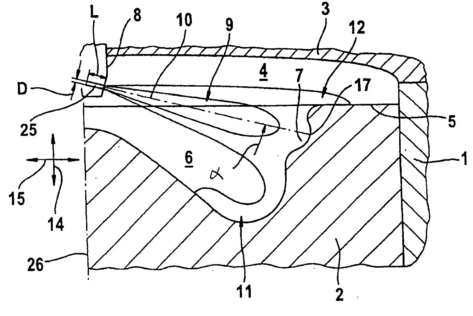
[0031]FIG. 1 shows a diagrammatic longitudinal sectional illustration of a direct-injection auto-ignition internal combustion engine designed according to the invention in the region of a cylinder 1 in which a piston 2 is moved up and down. Only one cylinder 1 is shown by way of example. The internal combustion engine may have any desired number of correspondingly configured cylinders 1, in each of which the method according to the invention, described below, is implemented.

[0032]A merely indicated cylinder head 3 delimits, together with the cylinder 1 and the piston 2, a combustion space 4. A merely indicated injector for the injection of liquid fuel, in particular diesel fuel, is arranged in the cylinder head 3.

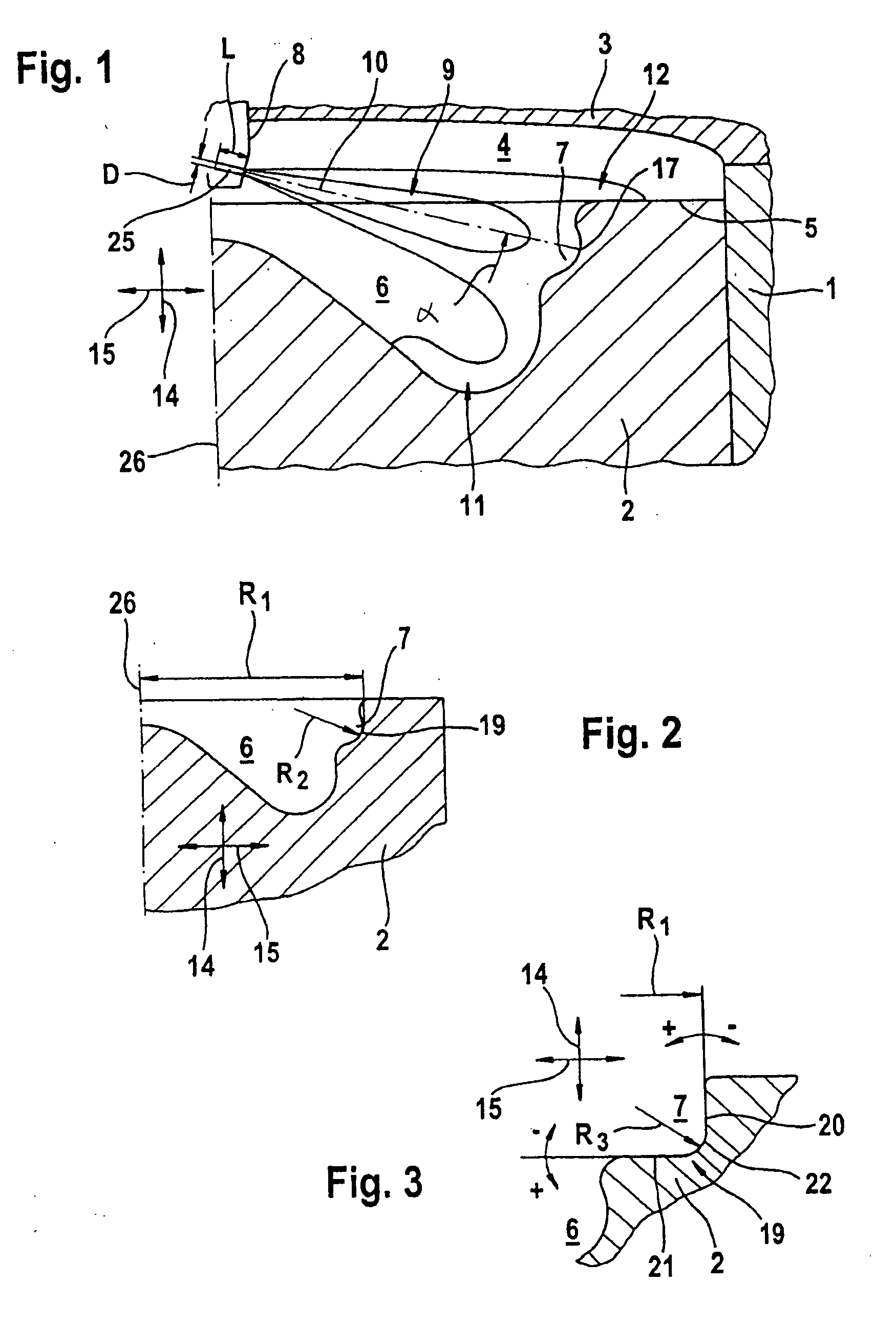
[0033]The piston 2 has, on its side facing the combustion space 4, a piston top 5 into which a piston recess 6 is formed. The piston recess 6 merges on the outside, in a radial direction 15, into an essentially annular stepped space 7 in the transitional region to the pisto...


PUM


Abstract

In a method for operating a direct-injection auto-ignition internal combustion engine and a correspondingly configured internal combustion engine including a piston top having integrally formed therein a piston recess which merges into an essentially annular stepped space and an injector forming injection jets directed toward the stepped space, the jets are deflected there in such a way that a first part quantity of fuel is directed in an axial direction and a radial direction into the piston recess, a second part quantity of fuel is deflected in the axial direction and the radial direction over the piston top and third part quantities of fuel are deflected into a circumferential direction so as to impinge one onto the other in the circumferential direction and to be deflected radially inwardly, the start of injection and the injection duration being coordinated with one another and with the crank angle of the internal combustion engine in such a way that the third part quantities of adjacent injection jets meet each other in the circumferential direction with a velocity of at least 15 m/s.

Description

[0001]This is a Continuation-In-Part Application of pending International patent application PCT / EP2007 / 00379 filed Apr. 28, 2007 and claiming the priority of German patent application 10 2006 020 642.8 filed May 4, 2006.BACKGROUND OF THE INVENTION[0002]The invention relates to a method for operating a direct-injection auto-ignition internal combustion engine having a combustion chamber delimited by the cylinder, the cylinder head and the piston of the engine, the piston having a special recess toward which fuel is injected into the combustion chamber, and to an internal combustion engine operated by the method according to the invention.[0003]DE 196 49 052 A1 discloses a diesel engine with direct fuel injection and with a piston recess. The direct-injection auto-ignition internal combustion engine shown there comprises at least one cylinder, a reciprocating piston disposed in the cylinder, a cylinder head and a combustion space delimited by the cylinder, the piston and the cylinder...

Claims


Application Information

Patent Timeline
Patent Type & Authority Applications(United States)
IPC IPC(8): F02B3/00
CPCF02B3/06F02B23/0651F02B23/0669F02B23/0693Y02T10/123F02B2275/14F02M61/1806Y02T10/125F02B23/0696Y02T10/12
Inventor ZOLLER, HERBERT
Owner DAIMLER AG
Why Eureka
Try Eureka