

Distributive Conductor
a distribution conductor and conductor technology, applied in the direction of insulated conductors, rigid-tube cables, cables, etc., can solve the problems of increasing the number of parts and assembling steps, and achieve the effect of reducing heat reflectivity, reducing assembling steps, and efficiently transferring
- Summary
- Abstract
- Description
- Claims
- Application Information
AI Technical Summary
Benefits of technology
Problems solved by technology
Method used
Image

Examples
first embodiment
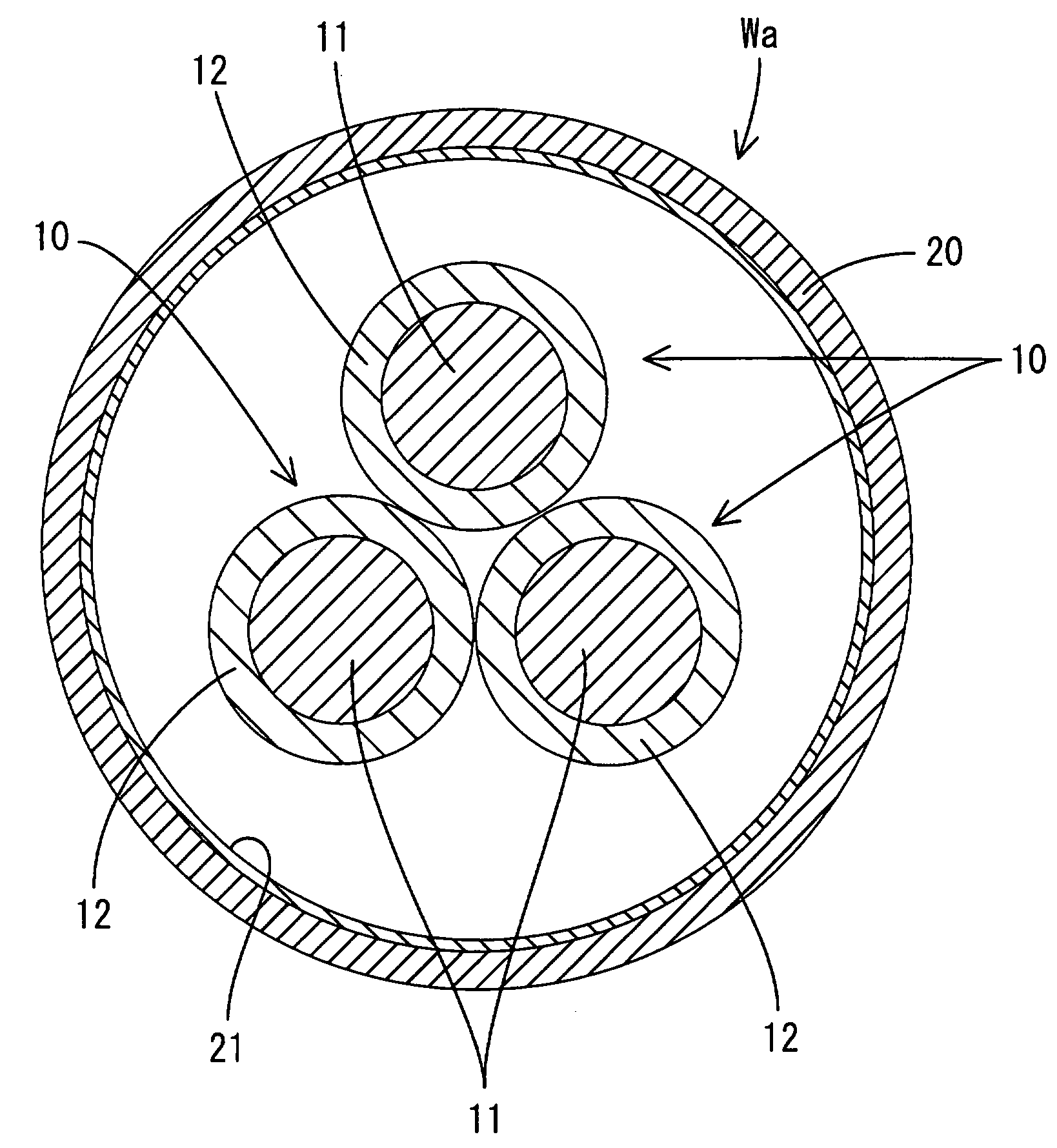
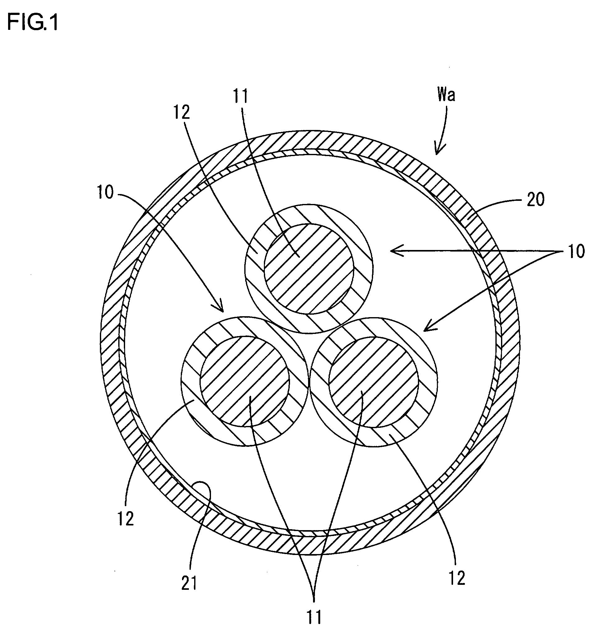
[0024]Hereinafter, a first embodiment according to the present invention will be described with reference to FIGS. 1 and 2. A shielded distributive conductor Wa according to the present embodiment is used in, for example, an electric vehicle as a motor circuit and the like positioned between an inverter and a driving motor, both of which constitute a driving power unit. The shielded distributive conductor Wa is formed by inserting three non-shielded insulated wires 10 into a pipe 20 that performs both a collective shielding function and a protective function for wires.
[0025]Each insulated wire 10 has a configuration that a conductor 11 made of metal (e.g., aluminium alloy or copper alloy and the like) has a periphery coated by an insulating coating 12 made of resin, while the each conductor 11 includes a twisted wire, which is made by twisting a plurality of thin wires (not illustrated) in a spiral matter, or a single core wire. In a cross sectional shape of each insulated wire 10, ...
second embodiment
[0034]A second embodiment is next described with reference to FIGS. 3 to 4. In a shielded distributive conductor Wb according to the present second embodiment, an inner circumferential wall of a pipe 20 is provided with a low heat-reflective layer 21, and an outer circumferential wall of the pipe 20 is provided with a heat dissipative layer 22. Both the low heat-reflective layer 21 and the heat dissipative layer 22 perform as means for improving the heat dissipation efficiency. Each of the low heat-reflective layer 21 and the heat dissipative layer 22 is constituted by a painted layer that is formed by applying black or similar to black (e.g. black ash) paint in a uniform thickness over all the inner or outer circumferential wall of the pipe 20. The low heat-reflective layer 21 is effective in higher heat absorption performance than the pipe 20, while the heat dissipative layer 22 is effective in higher heat radiation performance than the pipe 20. In addition, the low heat-reflectiv...
third embodiment
[0039]Next, a third embodiment according to the present invention is described with reference to FIG. 5. In a shielded distributive conductor Wc according to the present third embodiment, an outer circumferential wall of a pipe 20 is provided with a heat dissipative layer 22 as means for improving heat dissipation efficiency. The heat dissipative layer 22 is constituted by a painted layer that is formed by applying black or similar to black (e.g. black ash) paint in a uniform thickness over all an inner circumferential wall of the pipe 20, and is effective in higher heat radiation performance than the pipe 20. The low heat dissipative layer 22 is unicolor over all the outer circumferential wall of the pipe 20. Other constructions are the same as that of the above-described first embodiment, and therefore the same constructions are designated by the same numerals while the explanation of the structure, the operation and effect are omitted.
[0040]In the shielded distributive conductor ...
PUM
 Abstract
Description
Claims
Application Information