Method for manufacturing liquid discharge head

a liquid discharge head and manufacturing method technology, applied in the field of liquid discharge head manufacturing, can solve the problem of not getting desired supply characteristics, and achieve the effect of favorable supply characteristics and high shape accuracy

Inactive Publication Date: 2009-04-16
CANON KK
View PDF5 Cites 28 Cited by
  • Summary
  • Abstract
  • Description
  • Claims
  • Application Information

AI Technical Summary

Benefits of technology

[0008]The present invention is directed to a liquid discharge head

Problems solved by technology

However, in the case of where the large recessed portion serving as a part of the supply ports is formed on the substrate and then the small supply port is formed by dry etching from the rear surface of the substrate as discussed in U.S. Pat. No. 6,534,247, the

Method used


Image

  • Method for manufacturing liquid discharge head
  • Method for manufacturing liquid discharge head
  • Method for manufacturing liquid discharge head

Examples


first exemplary embodiment

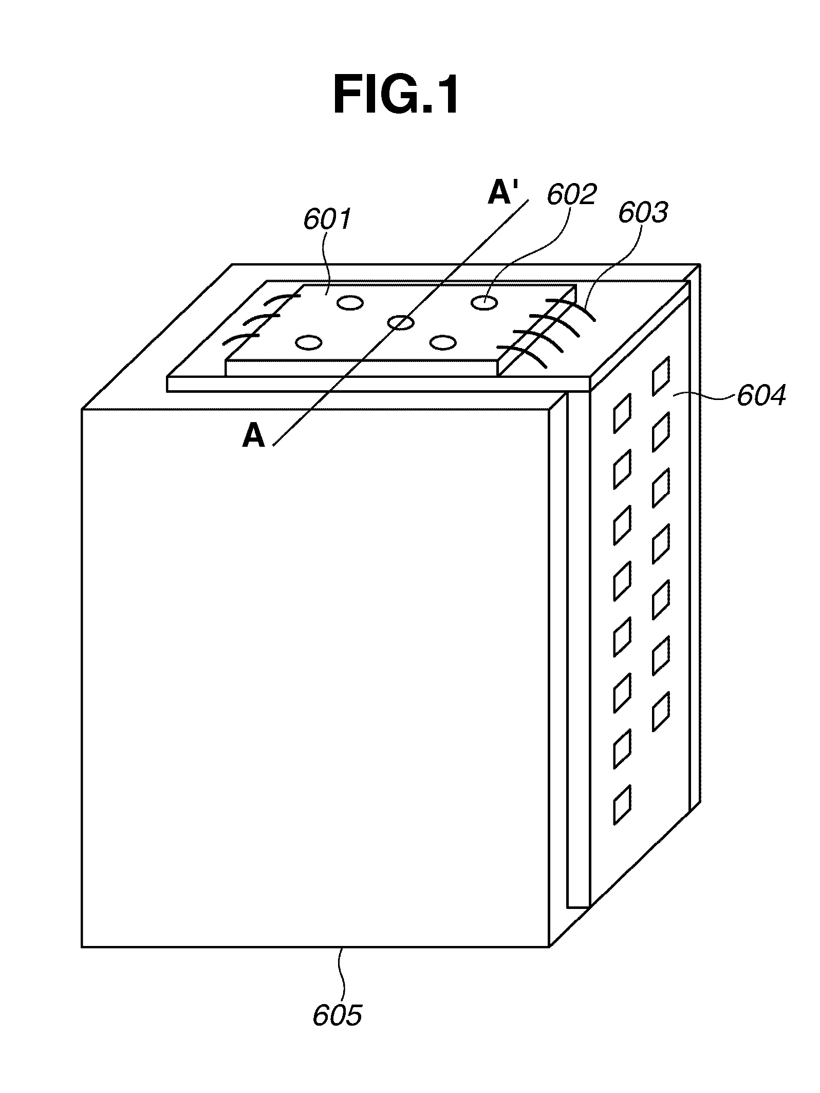
[0019]FIG. 1 is a perspective view illustrating an example of a liquid discharge head cartridge on which a liquid discharge head according to an exemplary embodiment of the present invention is mounted.

[0020]A tape automated bonding (TAB) film 604 sends / receives a recording signal to / from a main recording apparatus body. The TAB film 604 is provided on an outer surface of a holding member that detachably holds an ink tank 605. A liquid discharge head 601 having a plurality of discharge ports 602 is provided on the TAB film 604. The liquid discharge head 601 is connected to an electric wiring via an electrical connection lead 603.

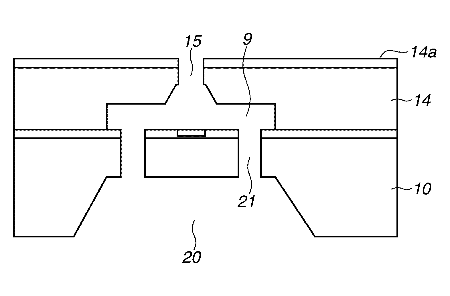
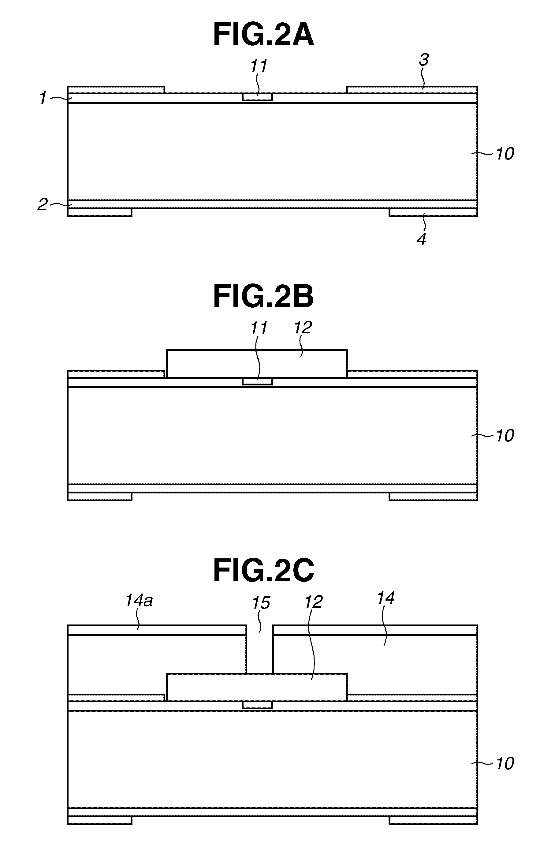
[0021]FIGS. 2A to 2H are sectional views illustrating an example of a method for manufacturing the liquid discharge head according to the first exemplary embodiment, in which a section corresponding to a section of a substrate taken along the line A-A′ of FIG. 1 is shown.

[0022]As illustrated in FIG. 2A, protection films 1 and 2 formed from a silicon oxide fi...

second exemplary embodiment

[0038]In the second exemplary embodiment, a flow path pattern is formed in a two-tier shape.

[0039]More specifically, the processes described referring to FIG. 2A in the first exemplary embodiment are first performed.

[0040]Subsequently, as illustrated in FIG. 4, a pattern of a flow path having a lower layer 212 and an upper layer 213 is formed on the substrate 10. The lower layer 212 is made from polymethyl isopropenyl ketone described in the first exemplary embodiment. The upper layer 213 is made from positive resist mainly containing a methyl polymethacrylate-based copolymer.

[0041]The subsequent processes are the same as the first exemplary embodiment, and a state illustrated in FIG. 5 is achieved by performing such subsequent processes.


PUM


Abstract

A method for manufacturing a liquid discharge head including a substrate on which supply ports for supplying a liquid are provided, includes forming a first supply port among the supply ports by performing crystal anisotropic etching on the substrate from one surface of the substrate, and forming a plurality of second supply ports among the supply ports by performing dry etching on the substrate using a crystal anisotropic etching method from a surface exposed toward the one surface of the substrate to a rear surface so that the independent second supply ports are respectively opened on the rear surface.

Description

BACKGROUND OF THE INVENTION[0001]1. Field of the Invention[0002]The present invention relates to a method for manufacturing a liquid discharge head for discharging a liquid, more specifically, to a method for manufacturing an inkjet recording head for performing recording by discharging ink onto a recording medium.[0003]2. Description of the Related Art[0004]As an example of a liquid discharge head, Japanese Patent Application Laid-Open No. 2006-130742 discusses a discharge head in which a substrate having an energy generating element which generates energy used for discharging ink is provided with supply ports for supplying a liquid to the energy generating element. In Japanese Patent Application Laid-Open No. 2006-130742, in order to improve liquid supply performance, small apertures that go from a part having a large volume to a surface of the substrate are provided in supply ports penetrating the substrate from a rear surface to the front surface. Each of the small apertures is ...

Claims


Application Information

Patent Timeline
IPC IPC(8): G11B5/127
CPCB41J2/1603B81C1/00523B41J2/1631B41J2/1628B41J2002/14467B41J2002/14403
Inventor KUBOTA, MASAHIKOOKANO, AKIHIKO
Owner CANON KK
Why Eureka
Try Eureka