Turbocharger mounting system

a technology for mounting systems and turbochargers, which is applied in the direction of machine supports, machines/engines, liquid fuel engines, etc., can solve the problems of reducing affecting the performance of the compression wheel, and affecting the performance of the turbocharger and other engine components,

Inactive Publication Date: 2009-04-16
INT ENGINE INTPROP CO LLC
View PDF25 Cites 11 Cited by
  • Summary
  • Abstract
  • Description
  • Claims
  • Application Information

AI Technical Summary

Problems solved by technology

The exhaust gases cause the turbine wheel to spin, thus causing the compressor wheel to spin.
If the turbocharger operates too fast, the turbocharger output can reduce engine performance and can damage the turbocharger and other engine components.
If the turbocharger operates too slow, the engine can hesitate, loose power, or otherwise operate inefficiently.
The connection between the turbocharger base and the internal combustion engine can be mismatched, such as when the turbocharger base and engine are uneven, when the holes on the turbocharger base do not align with the holes in the engine, and the like.
The turbocharger can be mounted on the engine when the turbocharger base and engine are mismatched, however the mismatched connection can create mechanical or installed stresses in the turbocharger and mounting mechanism.
In addition, the hot exhaust gases can cause thermal stresses during operation of the turbocharger.
The temperatu

Method used


Image

  • Turbocharger mounting system
  • Turbocharger mounting system
  • Turbocharger mounting system

Examples


Embodiment Construction

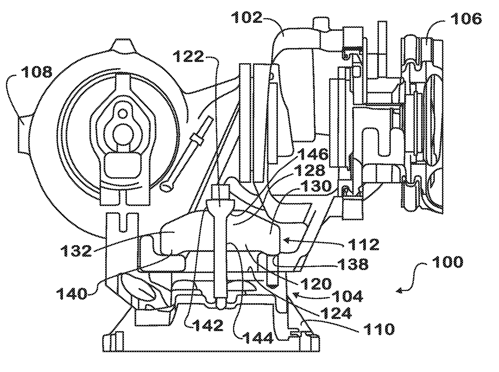
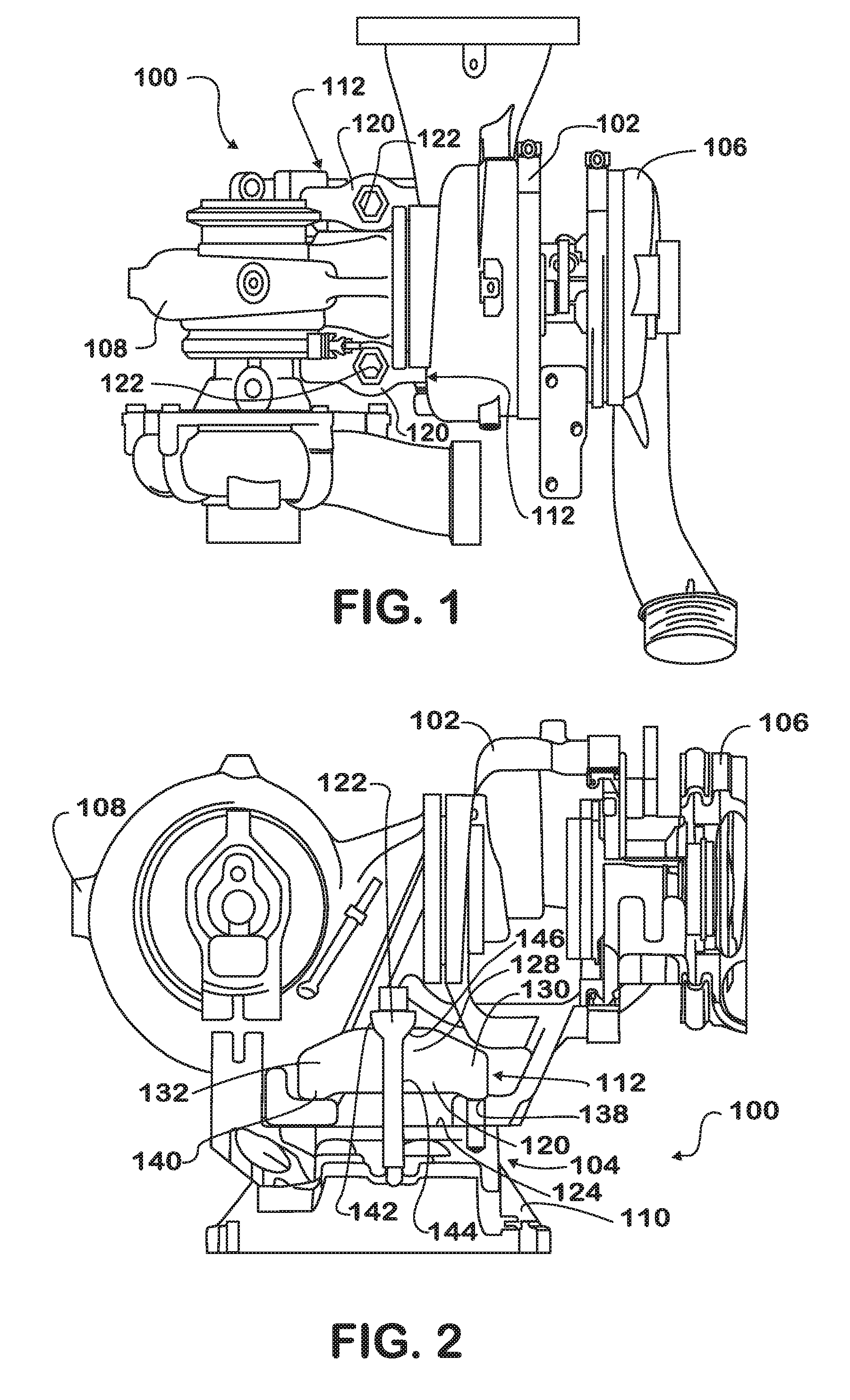
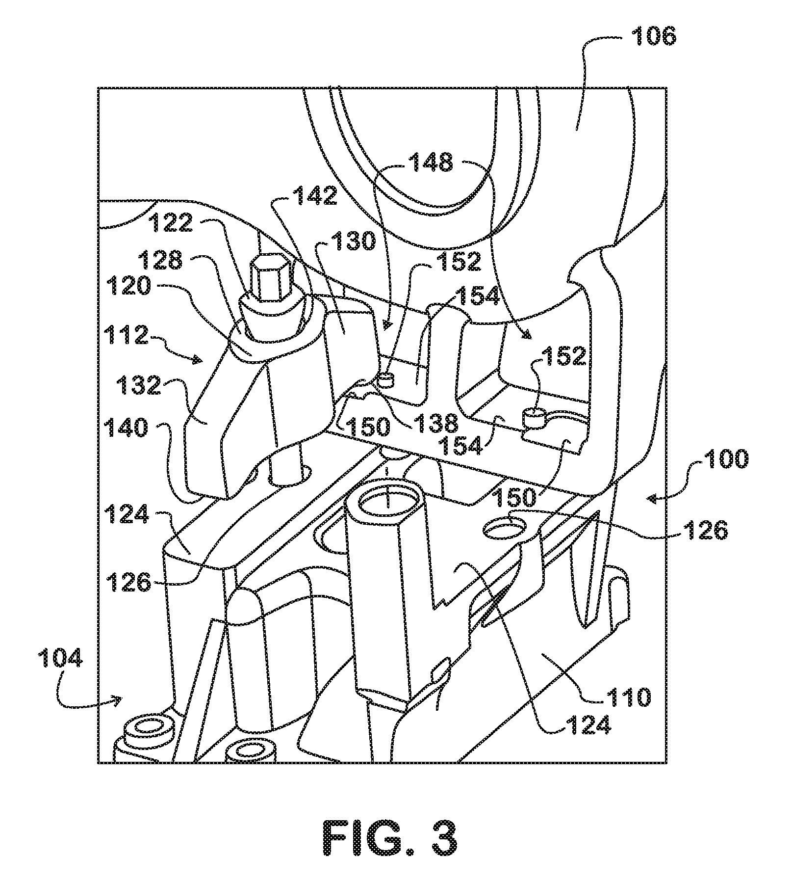
[0017]Referring to FIGS. 1 and 2, a turbocharger mounting system for an internal combustion engine is indicated generally at 100. The turbocharger mounting system 100 has a turbocharger unit 102 connected to a mounting mechanism 104. The turbocharger unit 102 is a dual turbocharger, having a first turbocharger 106 and a second turbocharger 108, however other configurations of dual turbocharger units are contemplated. Additionally, the turbocharger unit 102 can have other configurations such as a single turbocharger, a variable geometry turbocharger, and the like. In the turbocharger mounting system 100, the first turbocharger 106 can operate during high intake air pressures, and the second turbocharger 108 can operate during low intake air pressures.

[0018]The mounting mechanism 104 is connected to the internal combustion engine, such as with bolts, and is configured to mount the first turbocharger 106 and the second turbocharger 108 on the internal combustion engine with a degree of...


PUM


Abstract

A mounting system (100) for a turbocharger (106, 108) in an internal combustion engine includes a support base (110) having a top surface (134) configured for receiving the turbocharger and a recessed bearing surface (150) disposed on the turbocharger. The mounting system (100) also includes at least one bridging clamp (112) connected to the support base (110). The bridging clamp (112) includes a flange (120) having at least one wing (130, 132) that bears down on the bearing surface (150) of the turbocharger (106, 108).

Description

FIELD OF THE INVENTION[0001]This invention generally relates to turbochargers used in internal combustion engines. More particularly, this invention relates to turbochargers mechanically mounted on internal combustion engines.BACKGROUND OF THE INVENTION[0002]Internal combustion engines convert chemical energy from a fuel into mechanical energy. The fuel can be petroleum-based, natural gas, another combustible material, or a combination thereof. Most internal combustion engines inject an air-fuel mixture into one or more cylinders. The fuel ignites to generate rapidly expanding gases that actuate a piston in the cylinder. The fuel can be ignited by compression such as in a diesel engine or through some type of spark such as the spark plug in a gasoline engine. The piston usually is connected to a crankshaft or similar device for converting the reciprocating motion of the piston into rotational motion. The rotational motion from the crankshaft can be used to propel a vehicle, operate ...

Claims


Application Information

Patent Timeline
IPC IPC(8): F02B33/44F01D25/24
CPCF02B37/004F02B37/007Y02T10/144F02B39/00F02B67/10F02B37/013Y02T10/12
Inventor ANELLO, ANTHONY M.
Owner INT ENGINE INTPROP CO LLC
Why Eureka
Try Eureka