Selectively erasable electronic writing tablet

a technology of electronic writing and eraser, which is applied in the direction of writing boards, instruments, printing, etc., can solve the problems of consuming a lot of power, slow and inconvenient heat or flexing of the device to erase the image, and erasing the image, and achieve the effect of low device cos

Active Publication Date: 2009-04-16
KENT DISPLAY SYST
View PDF45 Cites 80 Cited by
  • Summary
  • Abstract
  • Description
  • Claims
  • Application Information

AI Technical Summary

Benefits of technology

[0013]This invention takes advantage of the unique threshold electro-optic behavior of the bistable cholesteric liquid crystal material. We have discovered that pressure created by a stylus resulting in a decrease of the inner electrode spacing can both create and erase an image in Mode A, B or multimode depending upon whether or not a voltage is applied during the application of the pressure. Because of thresholds in the voltage response curve of the bistable cholesteric liquid crystal, a suitable voltage or sequence of voltage pulses applied to the electrodes drives the liquid crystal material in the depressed electrode region of pressure to the focal conic state; erasing any image at the location where pressure of the erasing stylus is applied. At other locations not depressed by the erasing stylus, where the voltage response curve is un-shifted, the image remains unchanged. A selectively erasable writing device can employ buttons or switches that change the mode of the device to write images, selectively erase portions of an image, or fully erase all images from the display. An added advantage of this method of selective erasing is the low cost of the device since it only requires slight modification to the e

Problems solved by technology

A practical problem with the Hilsum device is erasing the image.
It is slow and inconvenient to heat or flex the device to erase the image.
However, this is not without problems in that crossover frequency between writing and erasing is strongly temperature dependent a

Method used


Image

  • Selectively erasable electronic writing tablet
  • Selectively erasable electronic writing tablet
  • Selectively erasable electronic writing tablet

Examples


example 1

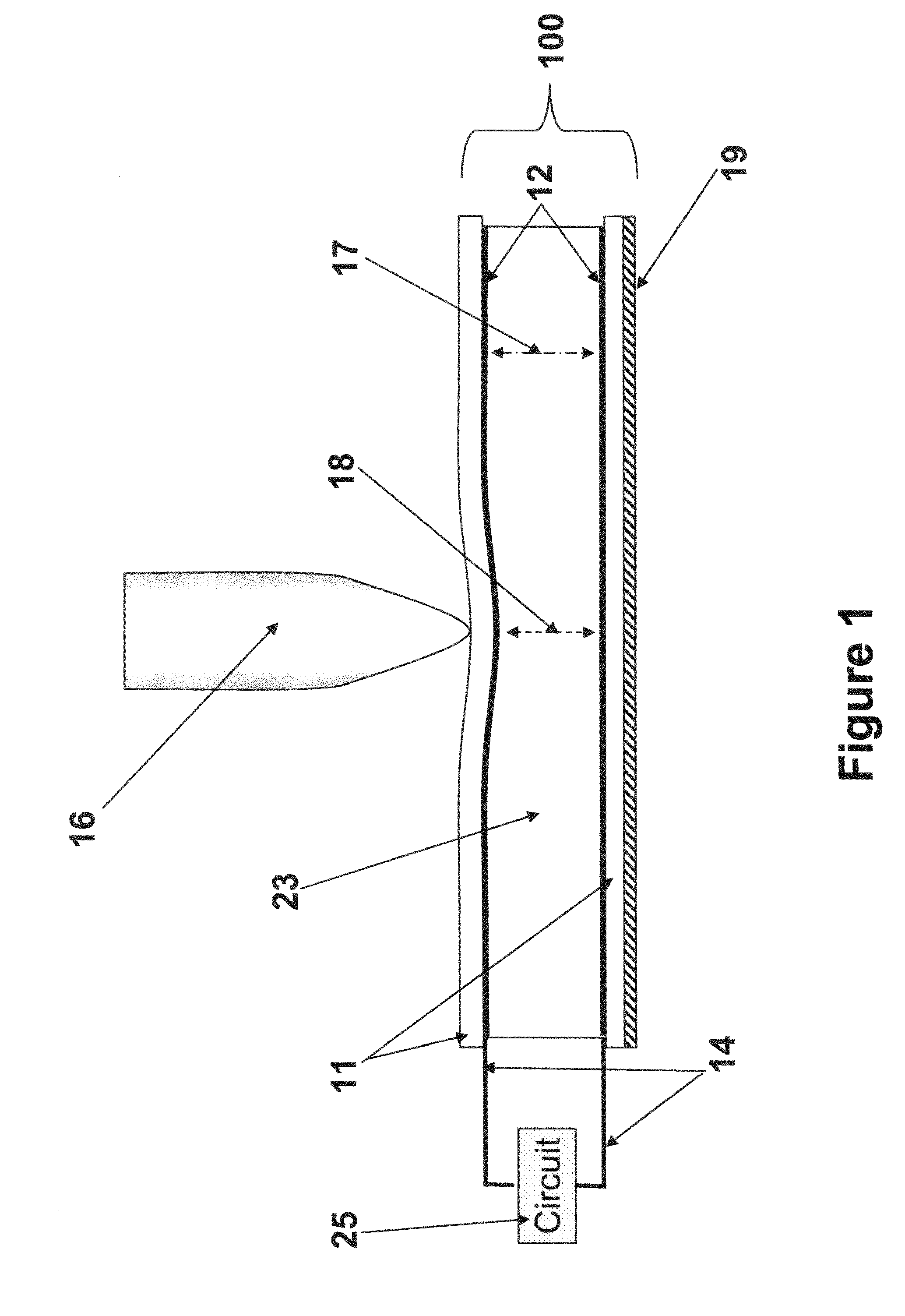
[0098]A bistable cholesteric writing tablet 100 (FIG. 1) was fabricated to demonstrate the inventive effect of utilizing the characteristics of the voltage response curve to write an image with the pressure of an untethered stylus comprising a written portion in the focal conic texture on a planar texture background. A writing tablet cell with a 4 micron cell gap was constructed from 2 substrates and an active layer. The top substrate was constructed from a 5 mil hardcoated thick Polyethylene Terephthalate (PET) (MacDermid, Inc.) and the bottom substrate consisted of a 7 mil PET (Piedmont Plastics, Inc.). Both substrates were coated with an unpatterned electrode made from a Meyer rod coated PEDOT-based conducting polymer (AGFA) that covered the entire surface area of the interior surface of both substrates. The active layer consisted of a polymer-dispersed yellow (580 nm) cholesteric liquid crystal (Merck).

[0099]The active layer of the writing tablet is made from a blend of polymeri...

example 2

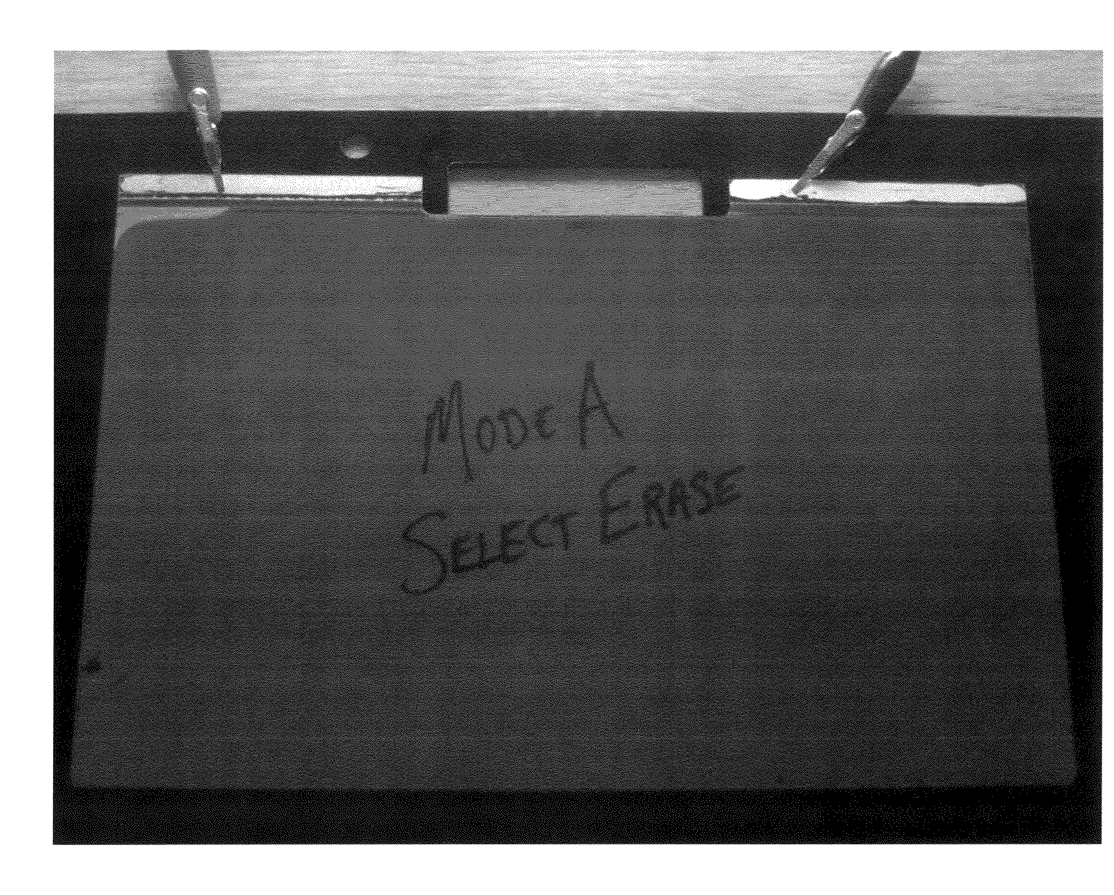
[0110]In FIG. 6, we can see the writing tablet from Example 1 switched to Mode B. Before writing, the display was switched to the focal conic state Vfc=18V (10 ms, 50 pulses) to erase any pre-existing information. Next “Mode B Select Erase” was written on the display including a line underneath the text while applying no voltage.

[0111]In FIG. 7, we can see the line underneath the text in FIG. 6 was selectively erased. This select erase of the line was achieved by applying a scanning voltage of Vw=9.5V (10 ms, 500 pulse), while re-tracing the line underneath the text with the stylus. It took 3 Vw scans to erase the image while retracing as the scans only lasted 5 seconds each. During the Vw scan and write, the liquid crystal underneath the stylus is re-written from the planar state back to the focal conic because of the reduced cell gap (and subsequently increased electric field). The selectively erased line under the text is barely visible in FIG. 7. Note that the text “Mode B Selec...

example 3

[0112]A double stack multiple color writing tablet, as schematically shown in FIG. 3 with both cells in Mode A was constructed using the same polymer dispersions as in Example 1, with the exception of different concentration of chirals in the cholesteric liquid crystals of cell 41 and cell 42 to achieve different colors. A first or upper cell 41 was constructed identical to the writing tablet cell of Example 1 with a 4 micron cell gap spacing except that the cholesteric liquid crystal (Merck) was selected to be one that Bragg-reflects blue light at a peak wavelength of approximately 470 nm. Furthermore, no background coating was placed on the upper cell so that all of the incident visible light that was not reflected by the cholesteric material of the first cell passed through it. A second cell 42 was constructed identical to the writing tablet cell of Example 1 with a 4 micron cell gap spacing and with the cholesteric liquid crystal that reflects yellow light at a peak wavelength o...


PUM


Abstract

An electronic writing tablet is composed of one or more layers on which an image is formed and can be selectively erased. One aspect of the invention is a bistable cholesteric writing tablet on which an image is formed while applying writing pressure. The image can be fully erased and new images written on the tablet. In addition, one can selectively erase any or all portions of the written image to restore the original background color. Another aspect of the invention is a multi-color stacked writing tablet in which a color of an image is selected (usually by applying a suitable voltage) while applying writing pressure using an instrument such as an untethered stylus on the surface of the tablet. The writing tablet includes at least two or three stacked layers of bistable cholesteric liquid crystal material. Selected colors can be additively mixed to achieve intermediate colors as desired. The image can be fully erased and new images written on the tablet. In addition, one can selectively erase any or all portions of the written image to restore the original background color.

Description

CROSS-REFERENCE TO RELATED APPLICATIONS[0001]This application is a continuation-in-part of U.S. patent application Ser. No. 12 / 152,729 filed May 16, 2008, which benefits from the priority of U.S. Provisional Application No. 60 / 962,625 filed Jul. 31, 2007, both of which are incorporated herein by reference in their entireties.FIELD OF THE INVENTION[0002]The invention relates to devices that can be written on with a finger or using a stylus or blunt instrument and a method of erasing or editing the written image.BACKGROUND OF THE INVENTION[0003]There have been various technological approaches to produce a writing pad as a replacement of paper and pencil or chalk on slate. The best known examples are toys. The ETCH-A-SKETCH™, introduced in the 1960s, is one such device. In this device, a movable stylus removes a powder material from inside a screen to make a dark line. The image is erased by turning the device upside down and shaking it to smooth out the surface. Another famous example...

Claims


Application Information

Patent Timeline
IPC IPC(8): G02F1/1335
CPCB43L1/00G02F1/13338G02F2001/13478G02F1/13718G02F1/13475G02F1/13478
Inventor SCHNEIDER, TOD L.MONTBACH, ERICADOANE, J. WILLIAM
Owner KENT DISPLAY SYST
Why Eureka
Try Eureka